PV Educational Kit for Academic Service Learning

Overview of System
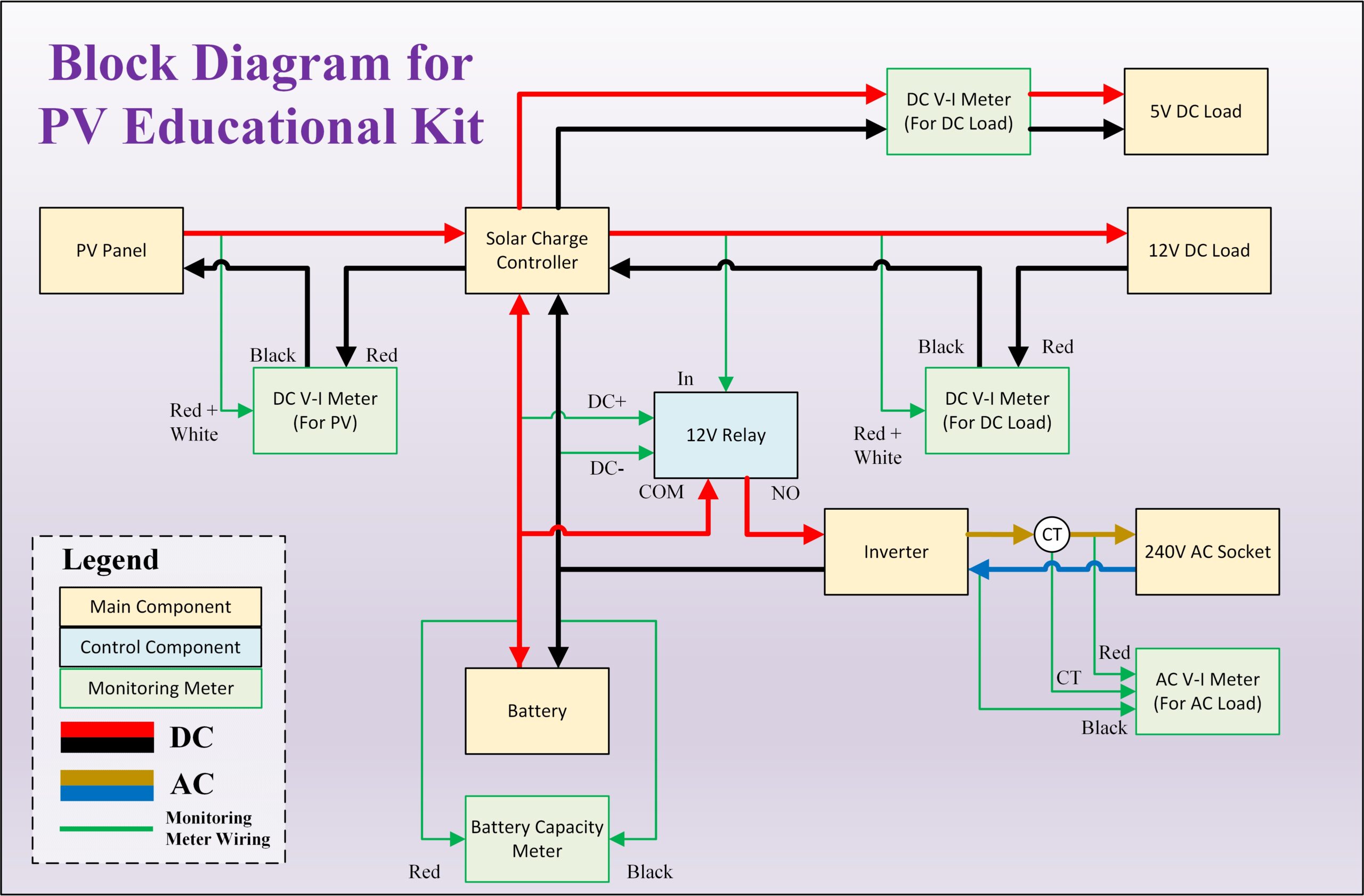
Block Diagram

PCB for Interface Board
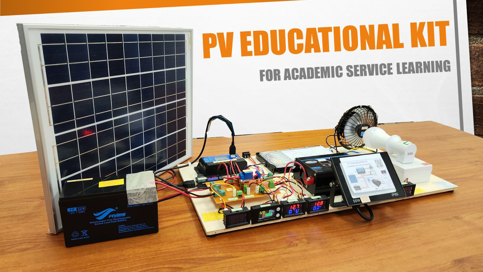
Hardware Implementation
About
Background of the Project
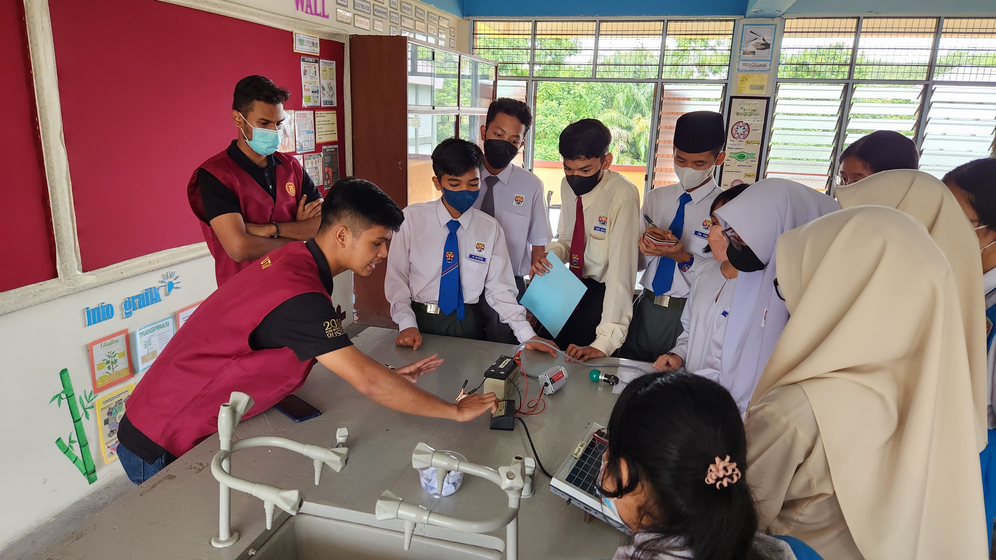
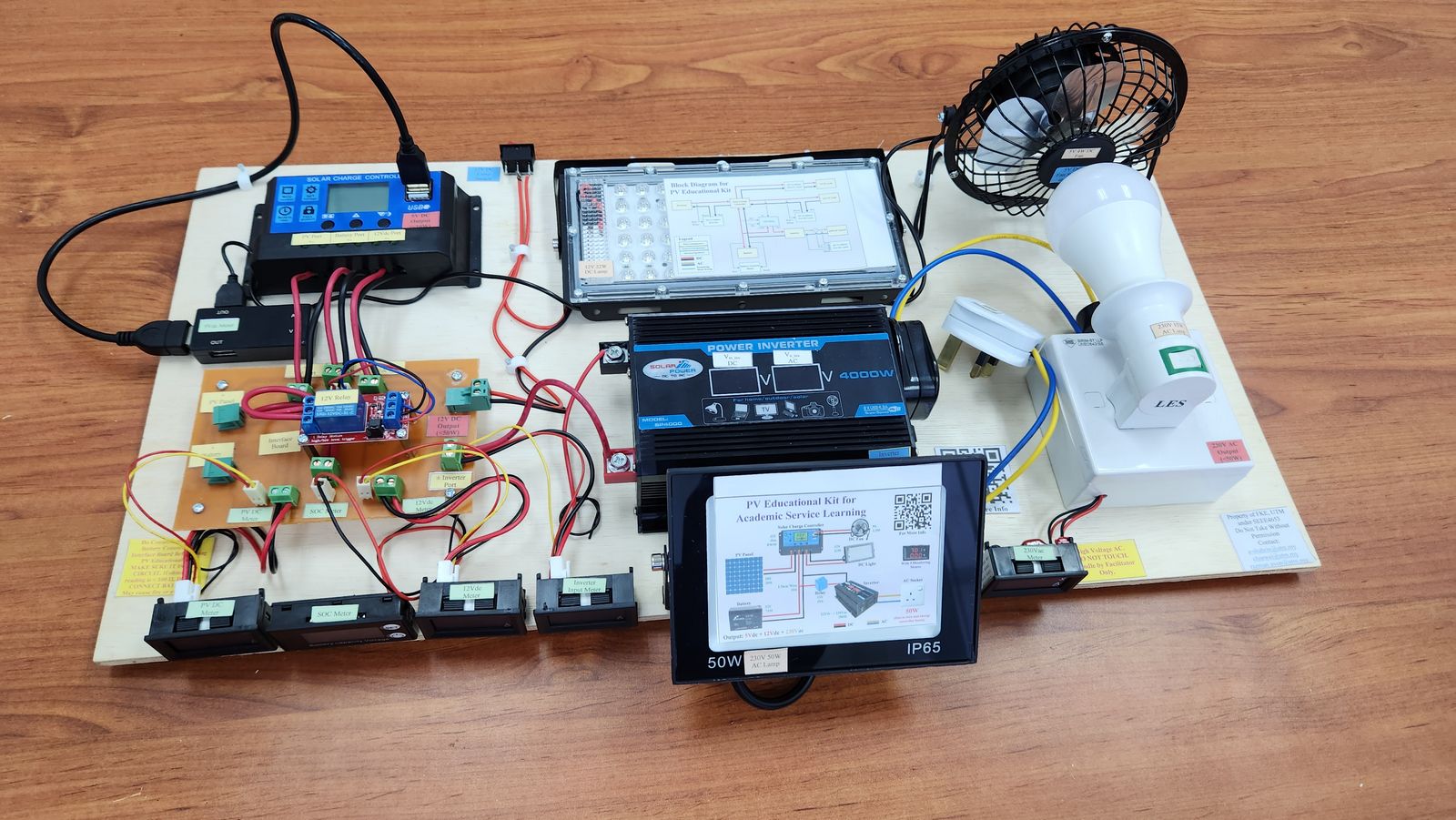
The PV Educational Kit is a 100W standalone PV system build on March 2023. It is sponsored by Faculty of Electrical Engineering, University Teknologi Malaysia on December 2023. The aim of the kit is to support the Academic Service Learning (ASL) program for the SEEE 4653 Photovoltaic and Wind Energy System course. The course requires the student to complete the ASL program at secondary school for 30% of their mark.
Problem Statement
Previously, the student uses a very simple, low cost, and low power (<1W) PV educational kit set such as PV fan, PV light, and PV car. There is also a simple and low power (5W) solar charge controller system without the inverter, which is not enough during ASL (60 secondary students per session). Besides that, the student unable to see the voltage and current for each part of the system since there no meters available during the demonstration. Although the secondary student able to learn a basic concept of PV in laboratory level, it does not show a how the PV system work at commercial level. Therefore, this PV educational kit can overcome the mentioned problem.
Objective of the Project
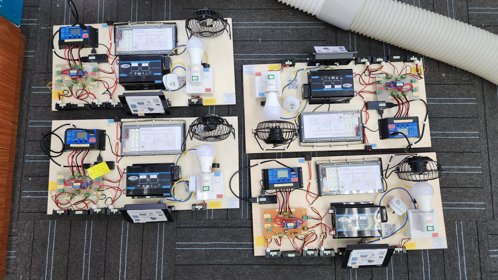
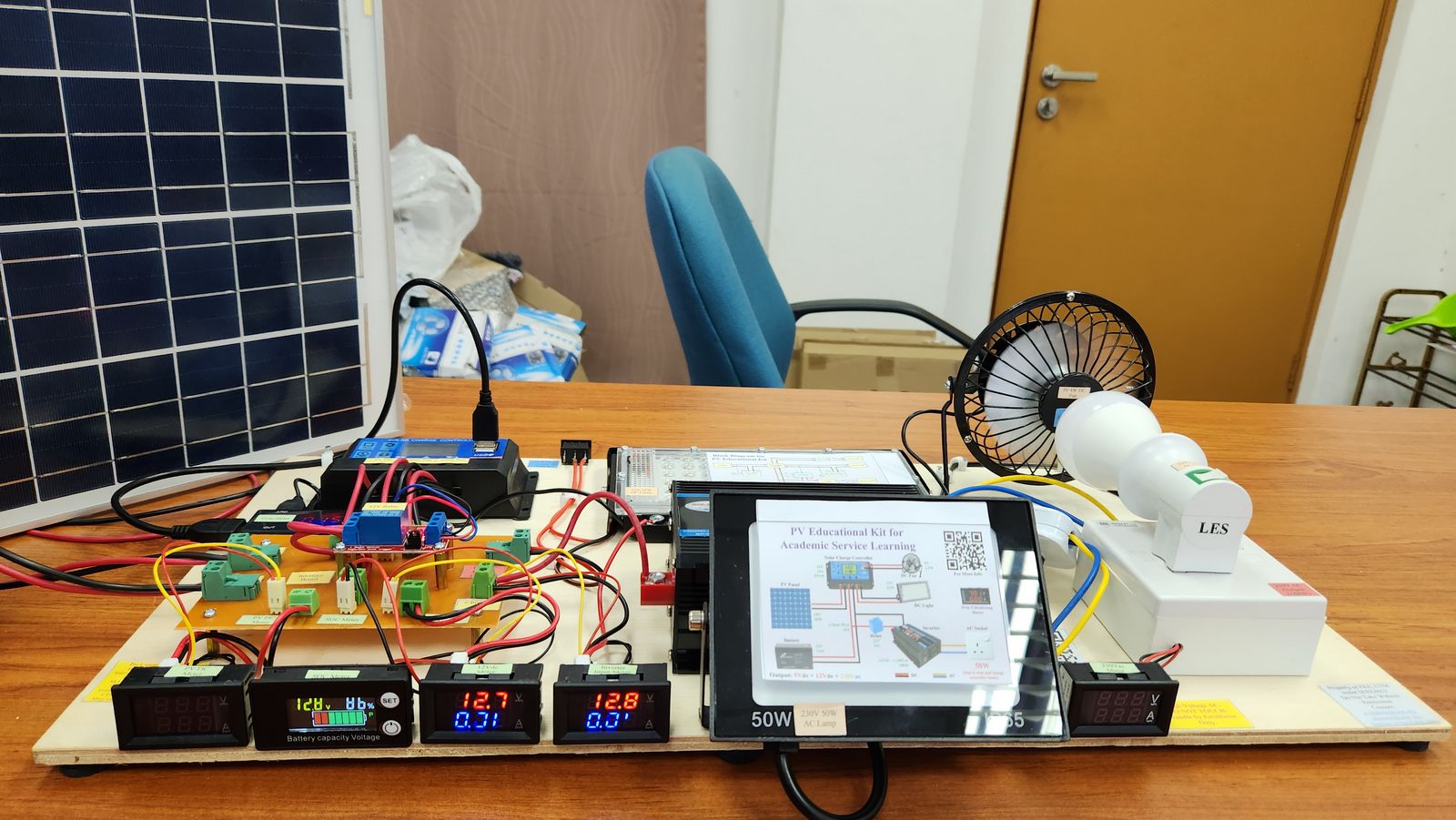
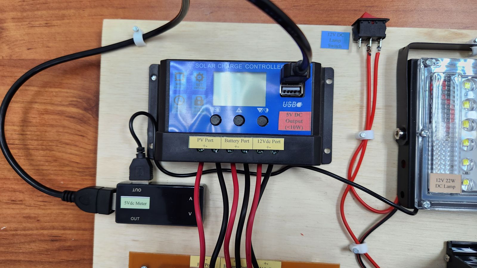
The objective of the project is to build 4 set of educational kits that represent commercial standalone PV system. The rating of the system is 100W 7Ah. The kit has 2 DC and 1 AC outputs, which is 5Vdc, 12Vdc, and 230Vac. The kit needs to have an independent voltage-current meter for PV and all outputs. The SOC meter is also included to determine the current energy capacity in the battery.

Focus Toward Theoratical and Not Practical

PV Car Toy

PV Fan and PV Light
Standalong PV System without Inverter
Scope of the Project
Several factors have been considered in the design of the PV educational kit. The standalone PV system is chosen due to the safety issues (standalone system is no connected to the utility supply) and regulation (grid connected system needs to have agreement with utility body, such as Net Energy Metering (NEM) or Feed-In Tariff). In practice, a solar inverter is used, which consist of only 1 device. However, for this educational kit, a separated system is used, which consist of solar charge controller and inverter. A separated DC-AC system is chosen due to cost constrain (separate system has smaller rating with lower cost) and educational opportunity (able to learn both DC-AC system and how the system works).
Operation of the System
The PV panel receive solar irradiance from the sun and converted into electrical energy. The energy flows to the solar charger controller. If the load from all outputs is lower than the power produce by the PV panel, the excess energy from the PV panel flows to the battery and the battery is charged. If the battery is full, the solar charge controller disconnects PV panel. If the load from all outputs is higher than the power produce by the PV panel, the insufficient energy from the PV panel is supported by the battery and the battery discharge. If the battery is depleted, the DC load is disconnected. The AC load is disconnected using relay. The inverter takes the 12Vdc from the battery and convert it into 220Vac.
Safety Precautions
- Make sure the battery is not short circuit. If this happen, the battery may catch on fire or explode. Do not remove the tape at the battery terminal. Check the resistance measurement at the battery port of the interface board. If resistance is less than 100 ohm, the system damage and cannot be used anymore.
- Be careful with the AC output since the voltage is high. Do not touch the expose part of the AC output. Make sure the person under 18 years old not handle the educational kit.
- If smell burning, quickly disconnect the battery. It may be caused by overload or short circuit.
- Make sure the input inductor current does not go more than 10A.
Operating Instruction
More Information on PV System


Frequently Asked Questions (FAQ)
Why the inverter is not connected directly into the load port of the solar charge controller, which result in additional component (12V relay)?
If the inverter is directly connected to the load port and the inverter is turned on, the solar charge controller and inverter will automaticly shutdown (safety feature). This is because the low cost inverter used here produce a high surge during turn on process. Therefore, the inverter needs to be connected directly to the battery. However, the solar charge controller cannot protect the battery when the battery is depleted. Therefore, the input of the relay is connected to the load port. if the battery is depleted, the load port is turned off, thus, turning off the relay and then the inverter.
Why there is an interface board added?
Based on the overall view of the system, the connection is quite simple. The connection needed to be added is only 10. However, this system does not show any information regarding the voltage, current, and battery state of charge, which is important for education purpose. To overcome this problem, 4 meters has been added to view these parameters. The meters show the Vpv, Ipv, Vdc, Idc, Vbat, SOC, Vac, Iac. By adding these 4 meters, additional connection needs to be added, which is now 21 connections (previously only 10 connections). Wiring using connection block is messy, as shown below. Therefore, the PCB is used to tidy up the kit.
Why the PWM type solar charge controller is used for the kit?
MPPT is an algorithm that extract power from the PV. It ensure optimum power is obtained from the PV. Without MPPT, the power extracted is lower (around 70%) only. This is due to the nonideal characteristic of the PV, which result in difficulty in extracting the power. Commertially, there are 2 type of solar charge controller, PWM and MPPT. PWM controller usually operate around the battery voltage. It is simpler and cheaper (around 3 to 5 times) compared to the MPPT. Due to budget constrain, the PWM is choosen for the kit.
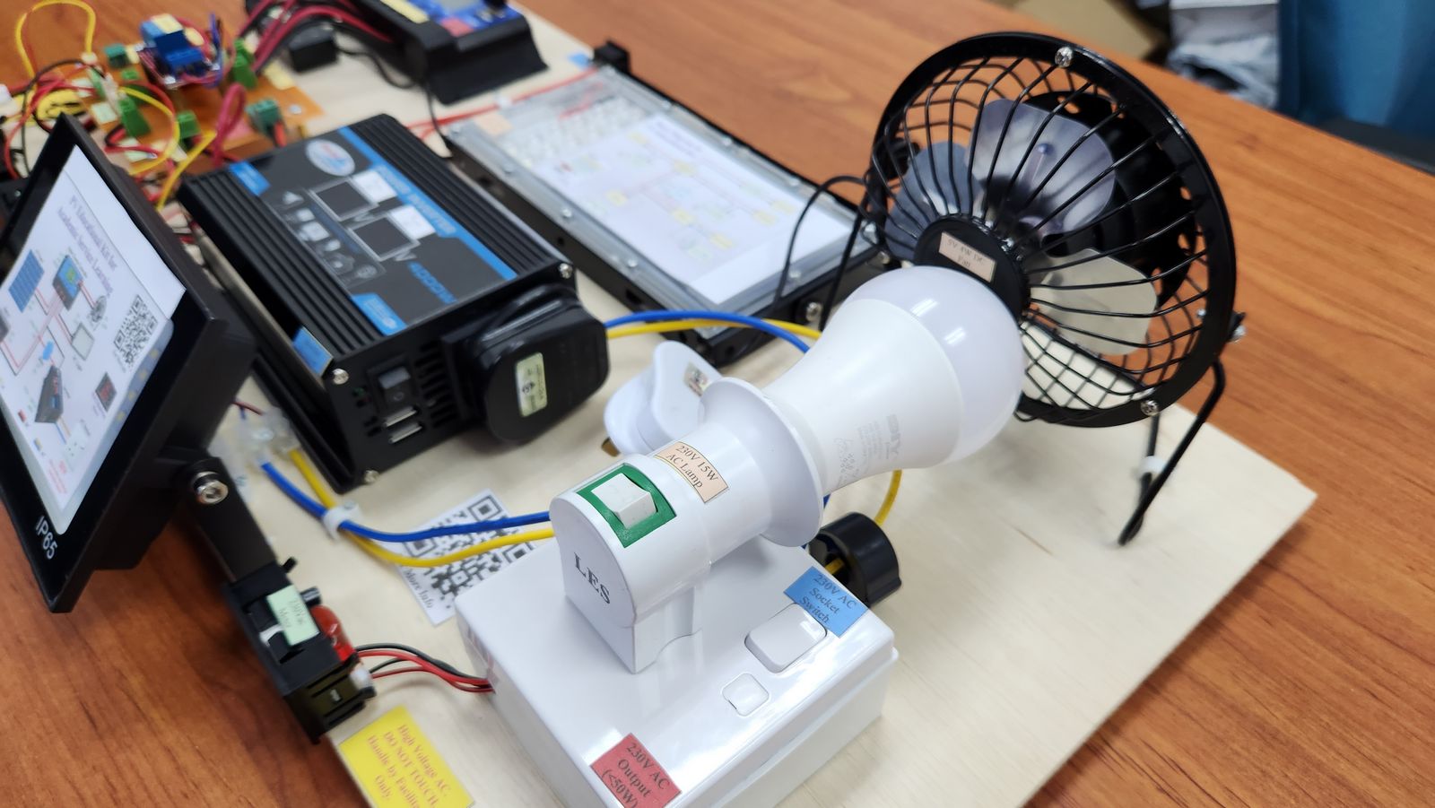
Why the current at AC meter is very low and why the AC socket only has 50W limit?
The provided AC lamp is only 15W. Using P = VI, and V = 230V, the theoratical AC current is only 0.07A. Using conservation of power theorem at the inverter, Pin = Pout, VinIin = VacIac and Vin is Vbat = 12V, the Iin becomes 1.25A. Although the current at AC site is only 0.07A, the current at the input of the inverter is already 1.25A.
For 50W load, the current at the input of the inverter become 4.17A. Since the rating of the wire is only 10A, higher rating can damage the system wiring. Assume the efficiency of the inverter is 80%, maximum theory of the AC socket power is 96W (0.42A). However, it can damage the system. Therefore, 50W limit is placed. Note that the inverter rating is 300W, and not 4000W (need to check the datasheet carefully when design a system. 4000W is just for surge only)
Why there are 3 output (5Vdc, 12Vdc, 230Vac)?
The diffeent output is needed due to the requirement of the load. Wrong supply used to the load may damage the load or the load unable to operate. Therefore, it is essential to connect the load to the proper output source.
Why the AC output is only 220Vac and not 230Vac?
The output voltage of the inverter is only 220Vac since it is the rating of the inverter. This is because the inverter comes from China and the voltage supply there is 220Vac. In Malaysia, the standard single-phase AC output is 230Vac. However, the standard (MS IEC 60038) allows voltage variation of +10% (253Vac) and -6% (216Vac). Since the 220Vac is within the voltage variation limit (216Vac to 235Vac), the inverter can still be used for electrical appliance in Malaysia.
Why the output is only single-phase and not 3-phase?
The cost of 3-phase inverter is very high. Besides, extra load needs to be added, resulting a much higher cost. The 3-phase inverter is also bulkier, which is harder to move around during the ASL activity.
Why there no current measurement for the battery?
Since battery current is bidirectional due to the charging and discharging process, the conventional current meter cannot be used. The bidirectional current meter is costly. Therefore, this meter is not implemented. However, the battery current can be calculated by using the equation (Based on Kirchhoff Current Law): Ibat = Ipv – (I5vdc – I12vdc – Ii_inv)
Why the measurement of voltage at inverter is different from the meter?
An accurate meter is very costly. Since the meter used is cheap, the reading is inaccurate. For accurate reading, high quality multimeter, such as Fluke, is needed.
Why the AC meter shows current reading even though no AC load is connected?
Since the AC meter is connected to the load site, the reading is caused by the meter itself using the energy. The meter requires a very high power to operate (around 80W) Make sure the the input inverter current does not go over 10A to avoid damaging the circuit.
What is the cost of the PV educational kit?
The cost for each set is around RM400 and requires 14 hours to build. It consists of 54 components for each kit.
