

This topology can produce 5-level using a single dc source and 6 unidirectional switches. The voltage of capacitor usually half of the Vdc value. The topology can be extended to 7 levels by simply insert a capacitor and 2 more switches. However, the sensorless capacitor voltage approach is quite impossible since there is no way in the topology switching that can be utilized to make sure that the capacitor voltage is always at V/3


During the conversion of AC to regulated DC output power, often the supply current will deteriorate. The harmonics contents are high and will not meet the standard. The power factor affected and the value will be very low. Low power factor draws more current from the main supply. We want to avoid that since the bills will be at a high amount. Something needs to be done to improve the power factor.
Active power factor correction using Boost dc-dc converter is the ultimate choice. The design is simple and the control is easy to understand. I have reached a website that clearly shows how this circuit works.
http://www.powerfactor.us/active.html
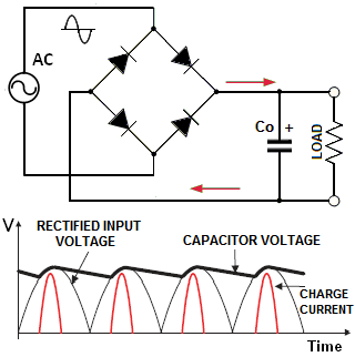
Active power factor correction (PFC) refers to the method of increasing power factor (PF) by using active electronic circuits with feedback that control the shape of the drawn current. There are many commercial PFC controllers that can accomplish this task. Let us first quickly review why we need to do it anyway. In conventional non-PFC AC-DC power supplies a large filter capacitor “Co” is placed directly after bridge rectifier (see the diagram below).

With that, in linear PSU the rectifier is connected via a low-frequency transformer, while in off-line switch-mode PSU it is fed from the AC input. In both cases, once “Co” is charged to nearly peak of rectified voltage, most of the time the diodes will be reversed biased and will not conduct. Therefore, such a PSU will draw power from the line in short pulses only when the instantaneous input voltage exceeds the voltage across the capacitor. This produces harmonics whose level can exceed an applicable standard (such as EN61000-3-2) and adversely affect other users.
In order to consume continuous sine-like current over the entire AC cycle, we can place an inductance before “Co”. In passive PFC the inductor is large and uncontrolled. It typically corrects the PF to 0.7-0.85.
In practice, a passive method is used only in small PSU (usually below 100W), when high PF is not required and regulation of DC-link is not neccesary.
In most other application an active method is used. This is a conceptual schematic of active PFC boost converter. The inductor “L” here is controlled by a solid state switch (denoted “Q”). This switch is driven ON and OFF by the control circuit at a frequency “F” much higher than the mains frequency. Let’s review how this circuit operates. During on-time “ton” the current in the inductor increases by ΔI+=Vin×ton/L. When the switch opens, the voltage across “L” reverses and it is releasing all or portion of accumulated energy via the diode “D”. During the off-time “toff” inductor current decreases by ΔI–=(Vo-Vin)×toff/L. The net change during one period “T” is ΔI=ΔI+-ΔI–=(Vin-Vo+D×Vo)/LF, where D=ton/T- duty cycle, F=1/T. We can see that by varying duty cycle “D” we can vary ΔI. If we do it properly, we can synthesize a desired I(t) shape.

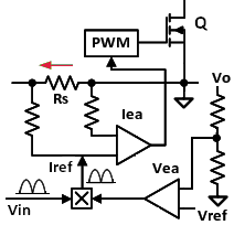
Here is a simplified block diagram of PFC control. Of course, commercially available PFC controllers contain many more functional blocks, but our example is sufficient to illustrate the basics of the operation. You can see an example of a complete PFC schematichere. The depicted circuit contains two error amplifiers- a slow one for voltage (Vea) and a fast one for current (Iea). A replica of rectified input waveform “Vin” is fed into the multiplier, which produces the programming signal Iref for Iea. The latter monitors the current via a sense resistor Rs and compares it to Iref. By varying control signal to pulse-width modulator (PWM), Iea forces average value of current to follow the shape of the mains voltage. The Vea monitors Vo via a divider and compares it to reference Vref. The error signal from Vea scales multiplier output up or down without changing its sine wave pattern. As the result, this circuit can perform two tasks simultaneously: it creates sine-like current and regulates the bus voltage Vo. The described method allows the designers to achieve PF as high as 0.99. Note that the described power factor correction technique addresses only line-frequency harmonics. You still need an EMI filter to reduce high-frequency components generated by switching mode operation of the power converters. This filter however may cause some negative effects. Particularly, its differential-mode inductors and across-the-line capacitors can introduce certain displacement angle between “Vin” and “I”, which is not corrected by the downstream PFC circuit. This effect may be unimportant if you have to comply only with EN61000-3-2, but could be an issue if in your application you also need to meet certain minimum PF limit.
Today I finish off the design of Cross-connected MLI. The switching is based on PWM. It is quite challenging at first on how to determine the switching for each switch.
https://www.mathworks.com/matlabcentral/fileexchange/86648-cross-connected-mli-with-pwm
This is a model that I created using Matlab software. It is a true power factor calculator where it uses real power measurement and distortion factor equations. It is suitable for nonlinear circuits, i.e., power electronics circuits.
Oops..I tried to attach it here, but it was blocked and not permitted. So I will give the link when available.
Today, 30th January 2021, I ran inside UTM. This is the only place where I can run peacefully without any disturbance or threat from stray dogs.
I tried running with the Maximum Aerobic Function (MAF). Alhamdulillah, that evening was my 2nd success in doing this training. I can run within my Aerobic zone. Amazing!
But for sure, my run’s pace is too slow compared to what I have had achieved. But nevermind on that..InsyaAllah,….run slower to run faster!
It will take time… a very long time to develop the basic. Once the basic gain strength, it is easy for me to accelerate the pace (according to what I have read ).
So, for the record. My average heartbeat was 144 bpm..maximum was 152 bpm! The pace was slow..it was 9 minutes plus. The range of my run is around 9km++.
An interesting multilevel inverter. Low active components. Able to generate 5-level output voltage with 6 switches only.


Alhamdulillah memulakan langkah pertama. Install MATLAB dan Arduino DUE configuration untuk communicate the MATLAB..memamng agak rumit jugak dan learning curve dia dah exponential dah..

Antara banyak banyak pintu masuk universiti di Malaysia yang pernah saya lawati, pintu UTM inilah yang saya rasa paling lawa dan unik
Petang tadi, selepas 5km run di dalam UTM, saya lihat langit amat baik dan ada ciri ciri sunset yang menarik nanti..sebab cuaca tengah panas, banyak awan..insyaAllah sunset yang cantik menanti… 🙂
