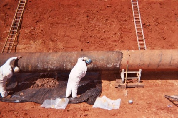
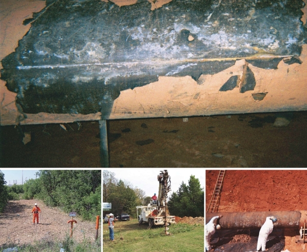
 An aging pipeline is being prepared for recoating. Photo courtesy of Jeffrey Didas.
The exterior of a buried pipeline is exposed to conditions that can lead to corrosion. Early on, pipeline operators began applying coatings to the pipe exterior at the time of installation to prevent corrosion. These initial pipe coatings were usually tape wraps, wax, asphalt, and coal tars. According to the U.S. Department of Transportation’s Pipeline and Hazardous Materials Safety Administration (PHMSA), two significant risk indicators for pipeline failure are the pipeline’s age and material of construction.3
Coatings are the main tools for protecting a pipeline against external corrosion, but they will weaken due to age and other factors. “All coatings have a service life,” says NACE International member Jeffrey L. Didas, a NACE-certified Specialist in coatings as well as cathodic protection (CP) and corrosion, and a senior corrosion engineer with MATCOR, Inc. (Chalfont, Pennsylvania). “Over time a coating will age and deteriorate due to soil stress, pipe movement, temperature changes of the pipe, and wet/dry, flood/drought conditions,” he adds. Didas notes that major pipeline construction from the 1940s to the 1960s mainly used coal tar enamel or asphalt enamel coatings for pipelines. Although these coatings had a predicted design life of 20 to 30 years, many have far exceeded this expected service life and are approaching or surpassing 70 years of age. Coating failures that have occurred tend to be cracking, disbondment, sagging, and melting from higher product temperatures.

Starting in the 1920s, pipeline operators determined that coatings alone would not provide complete corrosion protection and began installing cathodic protection (CP) systems to enhance the corrosion protection of their pipelines. A CP system applied in conjunction with a coating can also extend the service life of the coating. Typically this pipeline coating will be a dielectric coating, which is a barrier to the flow of electricity. A coating with higher dielectric strength—the voltage required to cause the coating to break down (which is expressed as V or kV per unit of thickness)—will provide superior isolation. The purpose of a dielectric coating is to isolate the pipeline electrically and physically from the environment, while reducing protective current demands on the CP system. Other properties necessary in a dielectric coating are resistance to environmental fluids and the product being transported, impact/abrasion resistance, adhesion, and resistance to cathodic disbondment.
As pipeline coatings age they start to lose their protective properties, such as elasticity and dielectric strength, and will crack or disbond, Didas explains. He comments that an increase over time in CP current requirements to cathodically protect the pipeline is a sign that a coating is deteriorating.
Evaluating a Pipeline Coating
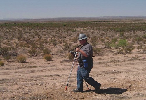
Typically, pipeline operators conduct an “on/off” close-interval potential survey4 (CIS or CIPS) of a pipeline about once every five years to assess the performance of installed CP systems vs. system performance criteria. A CIS can also be used to detect some coating defects.The principle of a CIS is to record the pipe-to-soil (P/S) potential (voltage) profile of a pipeline over its entire length by measuring the potential difference between the buried pipe and surrounding soil—with the CP current sources “on” as well as a synchronized interruption of the CP current sources (“off”)—at test point intervals that do not significantly exceed the depth of the pipe (often ~1 m). Measurements are taken while walking along the length of the pipeline. Didas notes that locations where there is little or no polarization of the pipe indicate the coating may be deteriorating, which can be seen by a downward (less negative) trend of potentials over time that require increased CP current to bring them back to a protective level. Areas where the coating appears to be failing can be further tested using additional aboveground techniques.
The downward potential trend, Didas says, usually prompts the operator to perform a direct current voltage gradient (DCVG) or alternating current voltage gradient (ACVG) test—aboveground methods of measuring the change in electrical voltage gradient (the voltage per unit length along a conductive path) in the soil along and around a pipeline to locate coating holidays and characterize corrosion activity.5DCVG and ACVG surveys evaluate in detail the coating condition on buried pipelines and identify and classify coating holidays. They are performed in those areas where the CIS indicates additional CP is needed.
With the CP system operating at its normal output, the DCVG technique applies a DC signal to the pipeline. Any defects in the coating will allow electric current to flow into the pipe from the surrounding soil. These currents cause voltage gradients in the soil above the pipeline, which can be measured using a voltmeter. Voltage gradients between two reference electrodes placed a distance apart are a result of current pickup or discharge at defect locations in the pipeline’s coating. DCVG surveys are capable of distinguishing between isolated and continuous coating damage.

Protective coating conductance techniques6 measure the coating conductance (inverse of coating resistance) on sections of underground pipelines and are also used to determine the general condition of the coating. This test method only applies to pipe coated with dielectric coatings. Conductance tests are performed whenever significant changes in P/S potentials and current requirements occur. Specific areas with high conductance values on a given section of pipeline indicate a deteriorated coating. To obtain data for coating conductance calculations, interrupted P/S potentials and pipeline current readings are taken at preselected intervals. Soil resistivity can directly affect coating conductance measurements and should be considered when evaluating a section of a pipeline coating.
Once the location of the coating defect is determined with aboveground techniques, visual and electrical inspection of in-service pipeline coatings can evaluate the condition and performance of an external coating system. These inspections can be conducted at bell holes (excavations shaped like an inverted bell, wide at the top and narrower around the pipeline to be examined) dug for inspection purposes. Many operators will also run an inline inspection with a smart tool to determine if there is corrosion where aboveground tests indicate the coating has deteriorated. “If you have a coating issue, you want to check out the internal inspection data, too.” Didas says.
Pipeline recoating is a proven method of rehabilitating pipelines with a deteriorated coating. It is considered the best long-term technical option for coating repair, and is required when the coating has failed and will no longer support CP, Didas says. At this point, he explains, the coating has completely lost its dielectric strength and too much CP current is needed to polarize the pipe. When done properly with a high-performance coating system, he says, recoating can increase the pipe’s service life by 50 or more years. When combined with CP, the service life could be extended to 100 years.
Recoating also can be the most expensive option, Didas adds, noting that recoating today can cost anywhere from $125 to $550 per linear ft (0.3048 m). Challenges associated with recoating a pipeline include pipeline excavation and right-of-way (ROW) conditions, which may be rocky, environmentally sensitive, highly populated, or in close proximity to other pipelines; environmental permitting; pipeline operating conditions; time of year (winter/summer); open blasting for surface preparation; handling and disposal of the removed coating; and landowner issues. As recoated areas of the pipeline increase, he notes, CP requirements should be reevaluated as well, since existing CP systems may need to be adjusted or modified for well-coated pipe.
Extending Aging Coating Life with CP

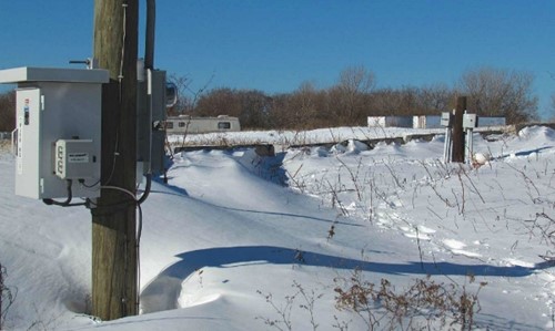
When the aging coating is not yet to the point where the pipeline requires recoating, installing a linear or distributed anode system to augment CP is a cost-effective option that provides protection for the pipeline as well as extends its life, says Didas. Typically, for cross-country pipelines, the impressed current CP (ICCP) design installed during construction is a remote anode bed that provides protective current for miles of pipeline. According to NACE member Norm Moriber, chief engineer with Mears Group, Inc. (San Ramon, California) and MP’s technical editor, the distribution of protective current down the pipeline, which is known as attenuation, is dependent on the resistances between the remote anode bed and the target structure’s surface. This causes the current density to decrease as the distance from the remote anode bed increases. When poor coating condition creates a localized area of low P/S resistance, providing adequate protective current to that area can be difficult. Increasing the current from the remote anode bed to keep potentials above criteria, however, can cause interference issues with neighboring pipelines, as well as overprotect areas of the pipeline closer to the anode bed, Didas warns. Also, the original CP design may not support the need for increased current at localized areas along the pipeline, Moriber adds.
A linear anode CP system resolves these problems by configuring the anode bed as a closely coupled structure that parallels the pipeline, Moriber says. “Overall, linear anodes provide a valuable tool for achieving cathodic protection for pipelines with an aging coating or other special requirements,” he comments. A linear anode is a continuous wire anode, typically comprised of a copper or titanium core and a conductive outer layer, and installed in a coke breeze backfill or prepackaged in a porous sleeve filled with coke breeze. The anode facilitates continuous current distribution along the length of the pipe surface, and its low-current output avoids the coating damage that can happen when trying to provide adequate current to distant locations from a localized anode bed, and excessive CP occurs near the current source. Linear anodes are closely coupled electrically with the pipeline, which minimizes current losses to nearby structures, helps eliminate stray current concerns, and also reduces current requirements for the system. Linear anodes can be installed by cable plow, directional drill, trencher, or backhoe and includes the anode and the header cable in the same installation.
A distributed anode system features individual graphite, cast iron, or MMO anodes, in various shapes and sizes, that are located close to the pipeline and spaced along its length (e.g., every 100 ft [30 m]), and interconnected with a header cable. Distributed anodes provide localized high-current output with an average resistance to earth and a high potential gradient. They can be installed by boring or backhoe and require the header cable to be installed between the anodes.

The primary factor for determining which type of anode system should be used is typically the pipeline’s ROW, says Didas. If plowing, trenching, or directional drilling can be accommodated, then the linear anode is usually the appropriate choice as it is more efficient and provides a uniform current distribution to the pipeline. Distributed anodes are used when ROW conditions allow only single anode installations because of rocky soil, limited easements, etc. The actual evaluation and selection of the CP system, including installation layout, current requirement testing, anode type, and installation method, should be performed by or under the direct supervision of a NACE-certified CP specialist or licensed corrosion engineer. The evaluation will determine whether a linear anode, distributed anode system, or a combination of both can be successfully integrated with the existing coating and recoated areas.
Adding well-designed CP with quality materials can extend the life of a CP system up to 50-plus years, Didas says. CP vs. recoating is a simpler fix and less intrusive on the pipeline ROW in areas where the pipeline coating is still compatible with CP. Considerations for installing additional CP are pipe accessibility, available electrical power, ROW conditions, the length of pipeline to be protected, and cost. A linear anode CP can be installed for ~$15 to $25 per foot for a typical pipeline ROW. The cost can go up to $50 per foot if the ROW has rocky conditions and there is a need for horizontal directional drilling.
Case History
Didas describes a case history where the asphalt enamel coating on a 255-mile (410-km) long U.S. pipeline, applied between 1960 and 1962 at the time of the pipeline’s installation, was reaching the end of its service life. The 32-in (813-mm) diameter pipeline transports refined products. Environmental factors along the pipeline’s ROW—soil stress, clay soil, rocky soil, and severe drought—had caused coating deterioration, disbondment, and failure over 35% of this line. The existing CP system incorporated conventional remote and close-coupled surface anode beds.
The pipeline integrity program called for conducting regular CIS surveys and other tests to monitor the pipeline’s CP potentials. Where survey results indicated possible coating deterioration, the pipeline owner would determine whether it was feasible and more economical to add CP, or if the section of pipeline needed to be placed on the recoating schedule. Didas notes that it is more cost effective to recoat segments of the pipeline as part of a plan rather than to reactively coat a section here or there; however, if there is a corrosion problem, timely mitigation must be implemented. Over a 10-year period, the pipeline was rehabilitated with recoating and CP. High-performance, two-part epoxy with a service life of 50 years was used to recoat 25 miles (40 km) (more than 98 segments) of the pipeline, the total amount of recoating deemed necessary after aboveground surveys and bell hole inspections were done, Didas says.
CP was added as follows: 195 miles (314 km) of linear anodes were installed in areas where the pipeline was responding well to CP and recoating was not necessary. Linear anodes were used because the existing coating had lost some of its properties—mainly attenuation—and the linear anodes were able to supply continuous current along the length of the pipeline segments. Twenty-one remote CP systems were installed perpendicular to the pipeline (with 500 ft [152 m] typically between the pipe and the first anode) in a conventional or surface anode bed configuration, with 20 to 30 anodes spaced 20 to 30 ft (6 to 9 m) apart due to varying soil resistivity, and buried 15 to 25 ft (5 to 8 m) deep. Two deep anode systems were installed where the ROW conditions did not allow the installation of a remote or linear anode bed and/or surface space was restricted due to possible CP interference issues or lack of an easement. Additionally, eight facility CP system upgrades were done with distributed anode systems, and 400 test sites were added. So far, Didas notes, the recoating and CP upgrades have proven to be successful. The entire CP system, in conjunction with the recoating, is 100% effective over the 255 miles of pipeline ROW. The rehabilitation of this pipeline segment is ongoing. Recoating is performed on a two-year cycle and additional linear anode CP is still being installed as the coating ages.
CP augmentation should be the first choice for pipeline rehabilitation if coating deterioration is addressed early enough, Didas says. The use of CP in lieu of recoating is a very cost-effective strategy for ongoing pipeline protection. Pipeline integrity can be restored using CP to supplement deteriorated coatings as well as protect the recoated segments. The engineering/design/evaluation analysis, however, should be done by qualified personnel to ensure the appropriate rehabilitation strategy is selected.
References
1 “The State of the National Pipeline Infrastructure,” U.S. Department of Transportation, https://opsweb.phmsa.dot.gov/pipelineforum/docs/Secretarys%20Infrastructure%20Report_Revised%20per%20PHC_103111.pdf (December 7, 2016).
2 “By-Decade Inventory,” Pipeline Replacement Updates, U.S. Department of Transportation, http://opsweb.phmsa.dot.gov/pipeline_replacement/by_decade_installation.asp(December 7, 2016).
3 “Background,” Pipeline Replacement Updates, U.S. Department of Transportation, http://opsweb.phmsa.dot.gov/pipeline_replacement/by_decade_installation.asp (December 7, 2016).
4 NACE SP0207-2007, “Performing Close-Interval Potential Surveys and DC Surface Potential Gradient Surveys on Buried or Submerged Metallic Pipelines” (Houston, TX: NACE International, 2007).
5 NACE TM0109-2009, “Aboveground Survey Techniques for the Evaluation of Underground Pipeline Coating Condition” (Houston, TX: NACE, 2009).
6 NACE TM0102, “Measurement of Protective Coating Electrical Conductance on Underground Pipelines” (Houston, TX: NACE, 2002).

Recent Comments