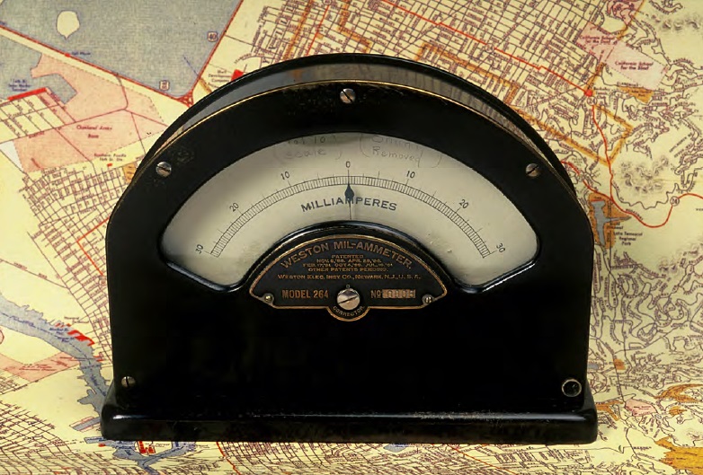
 The Weston Mil-Ammeter Model 264 was first patented in 1888.
Where the current left the pipe, it took metal with it, which led to rapid failure of buried water and gas pipelines. This phenomenon was referred to as electrolysis and was considered to be caused by “vagrant” or “vagabond” current, which is known presently as electrical interference or stray current. At the time, all corrosion of buried utilities was blamed on electrolysis, and many electrolysis departments, committees, and engineers came into existence as a result.

The East Bay Municipal Utility District (EBMUD) (Oakland, California), organized in 1923 to provide reliable, high-quality water for the people of San Francisco’s East Bay area, employed a corrosion engineering staff early on to help mitigate corrosion of its buried water pipe infrastructure. Known originally as the Electrolysis Department of the East Bay Water Co., this group helped pioneer the implementation of corrosion-control techniques for EBMUD, including the use of cathodic protection (CP) on large water transmission mains, which was groundbreaking at the time. Their corrosion laboratory was housed on the second floor of the District’s Claremont Center building, a critical pump station in Berkeley, California.

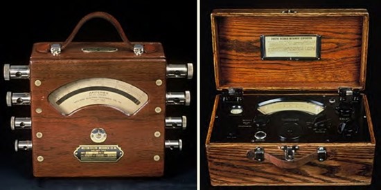
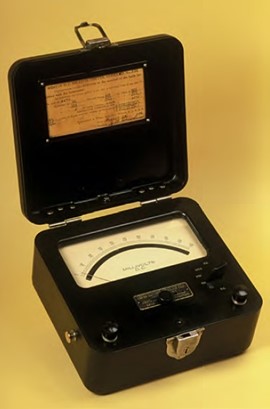
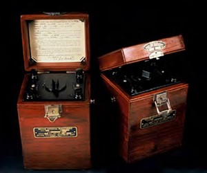
The instruments in this collection were used not only in the early studies of electrolysis,but were also witness to the emergence of electrical bonds as a method of corrosion mitigation. The electrolysis engineers recognized that bonding the rail to buried pipelines was one method of mitigating stray current. Where current flow was determined to be detrimental, they installed drainage bonds between the pipe and the rail itself, or at railway substations, to drain excessive current from the affected structure. In its simplest form, a bond was a wire that connected a rail to a buried pipe.

To monitor and manage this current exchange, amperage and voltage measurements were taken at bond stations using ammeters, voltmeters, and shunts. Ammeters measured the amount of electric current in amperes in a circuit. Voltmeters measured the electrical potential difference between two points in an electrical circuit. Shunts were used to measure current. When a shunt was placed in the wire or bond that connected the rail and the pipe, current passing through the drainage bond could be measured. By knowing the resistance of the shunt and measuring the voltage with a millivoltmeter, the amount of current passing through the shunt could be calculated using Ohm’s Law (I=V/R, where I iscurrent, V is voltage, and R is resistance).

Bibliography
Lewis, M. “How ‘Vagrant Current’ Became Impressed Current Cathodic Protection— Part 1.” MP 64, 11 (2008): p. 36.
Lewis, M. “How ‘Vagrant Current’ Became Impressed Current Cathodic Protection— Part 2.” MP 64, 12 (2008): p. 34.
Editor’s Note: Mark Lewis is the unofficial curator of EBMUD’s antique corrosion test equipment and instrumentation collection, which was on display during CORROSION 2013 in Orlando, Florida, USA from March 18 to 21 in the Exhibit Hall. The collection, generously on loan from EBMUD, is currently on display at NACE International’s Elcometer Building in Houston, Texas, USA.

Recent Comments