Cathodic Protection: Industrial Solutions for Protecting Against Corrosion

Cathodic Protection: Industrial Solutions for Protecting Against Corrosion

By Volkan Cicek (360 pages)

Price USD 175 (RM 750 – This book is available in the PSZ library TA418.74 C53)

A companion to the title Corrosion Chemistry, this volume covers both the theoretical aspects of cathodic protection and the practical applications of the technology, including the most cutting-edge process and theories. Engineers and scientists across a wide range of disciplines and industries will find this the most-up-to-date, comprehensive treatment of cathodic protection available. A superb reference and refresher on the chemistry and uses of the technology for engineers in the field, the book also provides a tremendous introduction to the science for new comers to the field


Assessing Galvanized Steel Power Transmission Poles and Towers for Corrosion

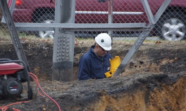
Mehrooz Zamanzadeh conducts a below-grade corrosion assessment of a buried tower leg. Photo courtesy of Mehrooz Zamanzadeh and BC Hydro Transmission.

The electric power utility industry commonly uses galvanized steel for power transmission poles, lattice towers, and other transmission and distribution assets—particularly high-voltage transmission line structures and substation structures—because it is known to be well-suited for service in most atmospheric and underground environments and has a long record of proven performance. According to the American Iron and Steel Institute, close to 1 million steel distribution poles have been installed in the United States since 1998 and are being used by more than 600 U.S. electric utilities.1

Zinc galvanizing protects the carbon steel (CS) substrate by providing a barrier against corrosive compounds and also by acting as a sacrificial anode that protects the underlying CS surface if the coating is damaged. Adelana Gilpin-Jackson, P. Eng., a specialist engineer with Canadian electric utility BC Hydro (Burnaby, British Columbia, Canada) comments that hot-dip galvanizing provides electric utility structures with a surface layer (Eta layer) of pure zinc for galvanic and barrier protection, as well as several intermetallic zinc alloy layers (Zeta, Delta, and Gamma) that form as the zinc coating is applied under high temperatures. These layers are metallurgically bonded with the steel to form a tough and well-adhered coating that provides superior galvanic and barrier protection.

Galvanized structures typically exhibit a low corrosion rate because a continuous passive film, known as a zinc patina, forms on the pure zinc top layer of the galvanized surface when it is exposed to the atmosphere. This passive surface film provides a protective barrier that prevents moisture and chlorides from corroding the underlying steel. As the patina starts to develop, a layer of zinc oxide (ZnO) quickly forms as the zinc reacts with oxygen in the air. The ZnO layer, when exposed to moisture, converts into a thin layer of zinc hydroxide [Zn(OH2)], which reacts with atmospheric carbon dioxide (CO2) over time and becomes a dense, insoluble layer of zinc carbonate (ZnCO3) that slows corrosion of the underlying zinc.

Above left: A corroded lattice tower foundation. Above center: Accelerated corrosion of a galvanized tower anchor due to stray current corrosion. Above right: Steel power transmission structures protected by galvanizing. Photos courtesy of Mehrooz Zamanzadeh and BC Hydro Transmission.

Above left: A corroded lattice tower foundation. Above center: Accelerated corrosion of a galvanized tower anchor due to stray current corrosion. Above right: Steel power transmission structures protected by galvanizing. Photos courtesy of Mehrooz Zamanzadeh and BC Hydro Transmission.

Since zinc is anodic to steel, the hot-dip galvanizing also acts as a sacrificial anode if the galvanized coating is physically damaged to some degree. If individual areas of underlying steel become exposed, the surrounding zinc will provide sacrificial cathodic protection (CP) to the unprotected sites by corroding preferentially. The zinc is consumed as it sacrifices itself to protect the bare steel.

Generally speaking, galvanized steel can last for many years in nonaggressive environments, and typically does an excellent job of protecting steel when the structure is located in moderately corrosive environments where oxidizing conditions prevail, says Mehrooz Zamanzadeh, FNACE, a NACE-certified Corrosion Specialist. He notes that during a recent field assignment in Texas, galvanized lattice towers dating back to the early 20th century were observed to exhibit an intact galvanized layer even after 90 years of service.

Zamanzadeh emphasizes, however, that the galvanizing on structures will corrode over time. The rate that the thickness of the zinc coating will diminish and the length of the remaining service life of the galvanizing—and the structure itself—are contingent on the active corrosivity of the environment. Several factors are associated with the corrosion rate of galvanized structures, such as the in-service atmospheric conditions to which the aboveground portion of the structure is exposed, and the soil environment where the structure’s foundation is buried.

Corrosion of a galvanized steel pole. Photo courtesy of BC Hydro Transmission.

Corrosion of a galvanized steel pole. Photo courtesy of BC Hydro Transmission.

Atmospheric environments considered corrosive include marine environments with salt-laden air, and industrial environments, which can produce acid rain as a result of industrial activity. In soil, corrosion activity can be accelerated by the soil’s chemistry (i.e., the presence of moisture and corrosive ions), its level of electrical resistivity, stray currents, and the nature and surface areas of grounding materials. Accelerated underground corrosion can also take place in the absence of oxygen due to the presence of bacteria or acidic soils.

Other factors are also associated with corrosion of a galvanized steel structure, Zamanzadeh notes, such as improper galvanizing thickness, excessive brittleness of the intermetallic alloy layer, general galvanizing failure, poor substrate surface preparation (especially if it was previously coated), storage conditions, installation damage, and unsuitable protective topcoat selection for the in-service soil or atmospheric exposure conditions.

Because deterioration of the protective zinc coating can lead to damage of the underlying CS structure, corrosion is a concern for galvanized transmission and distribution assets since it can lead to weakening of the structure, and then failure or collapse, says Gilpin-Jackson. A corrosion risk assessment can determine the environment’s corrosivity and the associated corrosion risk to galvanized steel structures. When evaluating transmission and distribution infrastructure for corrosion, individual assets should be assessed in order of their structural priority. Existing corrosion damage noted in the assessments should consider, among other criteria, the structure’s age, location, past history, its importance in the power system, future plans for the structure, and the safety and financial consequences if the structure fails.

Assessing for In-Ground Corrosion

A significant portion of corrosion mitigation activities for transmission and distribution structures is focused on the embedded portion of poles and towers, notes Gilpin-Jackson, since the assets’ foundations are critical to their stability and continuing service. Because foundations for existing structures are buried and out of sight, they could be deteriorating and close to causing a structural collapse—without any traditional inspector being aware of the problem. Zamanzadeh adds that determining corrosion risk in the structure’s deep burial area (~6 to 8 ft [1.8 to 2.4 m] underground) is often missed due to lack of knowledge about corrosion risk assessment. “It is often the case that utility inspectors perform only minimal testing, such as visual inspection and coating thickness measurements, to a depth of 2.5 ft (0.8 m) below grade. Unfortunately, these practices fall short in determining the condition of deep buried structures where accelerated corrosion may be taking place. We were recently involved in a case with a collapsed tower due to accelerated corrosion in deep burial that could have been avoided if adequate corrosion risk assessment procedures were in place,” he comments.

Below-ground corrosion risk is primarily contingent on the amount of moisture and corrosive ions in the soil or outside interference. For example, when the soil is dry, its resistivity is generally high enough to inhibit corrosion; however, when moisture conditions change at a site, soil resistivity can be altered and corrosion may accelerate. Although galvanizing steel has considerable resistance to corrosion when buried, corrosion attack can be initiated in soils that are reducing, acidic, or contain large amounts of corrosive, water-soluble salts. Generally, terrain with lower resistivity and reducing properties promote higher corrosion rates; however, it is important to define the corrosivity of the environment to determine the type of corrosion mitigation required and how often maintenance is needed, Zamanzadeh says.

Localized corrosion in a deeply buried foundation structure is caused by microbiologically influenced corrosion (MIC). Photo courtesy of Mehrooz Zamanzadeh and BC Hydro Transmission.

Localized corrosion in a deeply buried foundation structure is caused by microbiologically influenced corrosion (MIC). Photo courtesy of Mehrooz Zamanzadeh and BC Hydro Transmission.

To determine the corrosiveness of a soil, different soil characteristics and relevant attributes of the physical environment should be considered. This type of assessment combines corrosion and materials science, metallurgy, and electrochemistry, and correlates them with the structure’s design features; and then quantitatively determines the environment’s physical characteristics so a multi-faceted, risk-based corrosion assessment can be done. Assessments include testing the soil environment to rate its corrosiveness; conducting visual and physical condition inspections of buried structural components at a shallow depth; and electrochemically testing the interaction between the soil and steel (i.e., potential values and soil resistivity) to predict structural corrosion at deep burial depths.

The test results can be used to assign a below-grade corrosion risk rating or condition assessment value to each structure, which takes the structure’s age, size, design, function, and importance into consideration. The ratings then can facilitate the development of suitable remediation and mitigation procedures. Zamanzadeh notes the confidence level of the risk assessment, which indicates the ability of the technique used to produce reliable corrosion risk data, depends on the scope of the evaluation performed.

Geographic information system (GIS) data with geological records that summarize soil parameters can be used to conduct a desk study (pre-assessment). Soil data collected should include classification, resistivity, corrosivity, and pH. Because the accuracy and reliability of this assessment is based on the GIS source data and doesn’t necessarily account for terrain shifts, this study carries a low confidence level.

Testing actual soil samples taken around the structures’ anchors and footings can measure the resistivity and corrosivity of the soil, which determines the soil’s capacity to act as an electrolyte, as well as identifies the soil’s corrosion performance parameters, which indicate how actively it will corrode the steel. This type of assessment can be used to estimate maximum galvanizing thickness loss and predict the structure’s life expectancy under the worst possible conditions. Since the accuracy of the assessment depends on the location of the soil sample, the condition of the instruments, and the inspector’s skill, this type of study has a moderate level of confidence.

Knowledge-Based Assessment

Both Gilpin-Jackson and Zamanzadeh note that a knowledge-based assessment evaluates the structure as well as defines the surrounding environment. Because all relevant corrosion and structural parameters are measured in addition to a visual inspection during the detailed assessment, the level of confidence in this type of assessment is high. Parameters reviewed in this type of assessment typically include the structure’s characteristics, configuration, and expected performance; the site’s features from a corrosion and materials point of view, including the atmospheric and soil characteristics; and other external influences present, such as alternating and direct current interference (e.g., stray current), the presence of grounding, other land uses, etc.

Below-grade, deeply buried portions of power utility towers are subject to accelerated corrosion. Photo courtesy of Mehrooz Zamanzadeh and BC Hydro Transmission.

The galvanized structure is typically inspected visually to a below-grade depth of 36 in (0.9 m). If the structure shows significant signs of material loss at this depth, a more detailed condition assessment is performed using galvanizing thickness and adhesion measurements as well as defect characterization. Also, the maximum corrosion rate of the structural steel is measured using linear resistance polarization and electric resistance probes. Concrete inspection and petrographic analysis (if required) are performed for concrete base structures that are damaged or degraded.

“The knowledge-based assessment will let you know what mitigation techniques to use. Once you have all factual data, then you can make a recommendation—either implement corrosion mitigation, a repair, a replacement, or take no action,” Zamanzadeh comments. Additionally, he adds, the knowledge-based assessment can guide the inspection schedule for the structure so the scope of work over several years can be planned, funded, and staged.

Similarly, Gilpin-Jackson notes that owners want to be sure they invest upfront on corrosion mitigation for new structures that is appropriate for the in-service conditions. Because corrosion mitigation activities are increasing, so is the recognition that knowledge-based mitigation is vital.

Painting over galvanized steel transmission and distribution structures that have been in service for many years can extend the life of the zinc coating. For all cases where a structure is buried in corrosive soil, the galvanized steel should at least have a suitable topcoat applied to protect it against the adverse effects of higher-than-normal soil moisture/corrosivity, says Zamanzadeh. He recommends that a factory-applied, organic coating, such as polyurethane or other environment-resistant coating, be specified for galvanized steel structures in contact with corrosive soil. For more robust corrosion mitigation results, he suggests a CP system be added for each such structure, and notes this corrosion mitigation combination has proven to provide a stronger failure-safe solution than either a protective coating or CP alone.

Assessing and mitigating the corrosion before it causes a structural issue is vital. Monitoring the galvanized layer thickness will indicate the zinc coating’s remaining service life and provide a time guide for applying a protective topcoat. Typically, a structure won’t need to be topcoated until a significant portion of the galvanizing’s surface zinc is depleted, which could take 30 to 40 years depending on the service environment, says Zamanzadeh. Then, maintenance recoating should be considered when the galvanized steel’s top-most intermetallic galvanized layers—the Eta, Zeta, and Delta layers—are corroded. Generally, if the galvanizing’s Gamma layer (the layer closest to the substrate) is depleted, then structural corrosion may have initiated and it could be too late to paint without further steel assessment and possible steel replacement, notes Gilpin-Jackson. If structural corrosion is present, the load-bearing members may need to be replaced to protect the structure’s integrity. In extreme cases, the entire structure may need to be replaced.

Developing a long-term corrosion mitigation and maintenance plan based on a knowledge-based assessment can cost-effectively extend the life of galvanized steel transmission and distribution structures and prevent catastrophic failures. Plans should include future inspections, coating, CP, mechanical repairs, and other corrosion mitigation procedures where feasible.

More information on assessing galvanized steel for electric power utility transmission and distribution structures, including a case study that describes the application of a system-wide CP system for aging galvanized poles with below-grade corrosion, can be found in CORROSION 2016 paper no. 7245, “Galvanized Steel Pole and Lattice Tower Corrosion Assessment and Corrosion Mitigation,” by M. Zamanzadeh, C. Kempkes, D. Riley, and A. Gilpin-Jackson.

Contact Mehrooz Zamanzadeh, Exova—e-mail: zee@exova.com; and Adelana Gilpin-Jackson, BC Hydro—e-mail: Lana.Gilpin-Jackson@bchydro.com.

Reference

1 “Utility Poles,” Steelworks, the Online Resource for Steel, American Iron and Steel Institute, http://www.steel.org/the-new-steel/utility-poles.aspx (November 4, 2016).

Applying Cathodic Prevention to Electric Transmission Tower Foundations

The galvanostatic pulse method measures corrosion current density and resistivity of the concrete.

 Electric transmission tower foundations have a great impact on the stability and performance of the towers. Without having sound and safe foundations, these structures cannot perform the functions for which they are designed. Reinforcing steel bars (rebar) in concrete foundations for power transmission towers also act as the ground electrodes during current faults.1

Corrosion assessment, lifetime estimation, and corrosion protection of concrete structures are very important issues in corrosive areas. As an example, Iran operates more than 125,908 km of overhead power transmission and subtransmission lines (>63 kV).2Approximately 19% of these high-voltage lines are located in corrosive coastline environments (Figure 1). Around 17% of these high-voltage lines are more than 30 years old.3 Operation of power transmission lines is controlled by regional electric power companies. One of the companies, Hormozgan Regional Electric Co., spends more than US $400,000 annually to repair and rehabilitate nearly 1,000 corroded tower foundations.4

FIGURE 1: An important sea-crossing mast that transmits electricity to Iran’s biggest island.

FIGURE 1: An important sea-crossing mast that transmits electricity to Iran’s biggest island.

Corrosion and Cathodic Protection of Steel in Concrete

When chlorides reach the steel surfaces inside reinforced concrete structures, active corrosion leads to the formation of expansive corrosion products, resulting in cracks of the concrete cover. It takes only a small amount of corrosion metal loss (e.g., ~0.1 mm) at the rebar surface to create corrosion products sufficient to generate internal stresses that crack the concrete (Figure 2).5

Cathodic protection (CP) is the most effective method of controlling ongoing corrosion in reinforced concrete structures. By applying cathodic polarization, the corrosion potential is shifted to the region of immunity in the Pourbaix diagram; and corrosion is stopped from a practical point of view.6

FIGURE 2: A severely cracked electric distribution tower foundation.

FIGURE 2: A severely cracked electric distribution tower foundation.

The application of CP to a reinforced concrete structure transforms the environment around the steel reinforcement over a period of time. The metal surface becomes negatively polarized, thus repelling chlorides; oxygen and water are consumed; and hydroxyl ions are generated at the metal surface. The hydroxyl alkalinity restores the pH at the metal surface, inducing passivity of the metal.7

Investigations

Evaluations were conducted on 152 selected electric transmission tower foundations located along Persian Gulf coasts. A variety of parameters were measured for corrosion assessment. These parameters included effects of the environmental conditions, as well as the concrete’s structure and properties, on the degree of damage caused by steel corrosion.

During this investigation, NACE SP0308-20088 guidelines were followed. After checking the repair history and visual inspection, data on each foundation were collected for the following parameters:

• Age

• Distance from sea

• Height above the sea level

• Concrete cover depth

• Rebar diameter

• Alkalinity

• Chloride ion concentration

• Concrete homogeneity and compressive strength

• Soil resistivity

• Corrosion potential

• Corrosion current density (CD)

• Concrete electrical resistivity

Alkalinity (pH) and chloride ion concentration were determined from concrete powder obtained by drilling three 30-mm diameter holes, each 25-mm deep. Alkalinity and chloride content values were obtained by averaging the values of three tested samples. According to ASTM C1218-15,9 water-soluble chloride content is used as an applicable parameter related to corrosion occurrence.

The concrete homogeneity and strength were estimated using the Schmidt hammer. The values for cement content and water/cement ratio were obtained from design documents. Since water content in the mix design is a significant parameter affecting structural durability, it was also obtained from design documents and considered in the evaluation.

Soil resistivity and corrosion potential were field-measured according to ASTM G57-0610and ASTM C876-09,11 respectively. The galvanostatic pulse method was used to measure corrosion CD and resistivity of the concrete (Figure 3).

FIGURE 3: Galvanostatic pulse measurements determine corrosion potential, corrosion rate, and concrete resistivity.

FIGURE 3: Galvanostatic pulse measurements determine corrosion potential, corrosion rate, and concrete resistivity.

The average temperatures and relative environmental humidity are similar throughout the locations investigated, so the influence of these parameters on the rebar corrosion was not considered.

Results

Table 1 shows typical results for one of the selected foundations. The data for each parameter were then analyzed and 
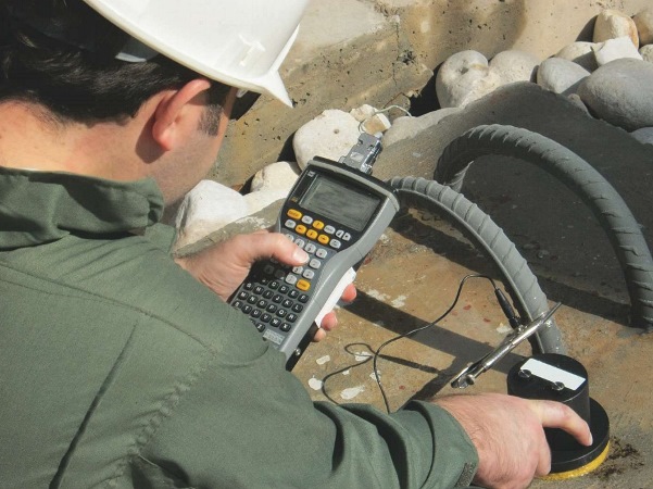
processed by software developed in-house based on an artificial neural network. This software classified the examined tower foundations into one of four corrosion risk categories (low, medium, high, and very high). The results showed ~60% of the selected foundations were placed in either the high or very high corrosion risk groups.

In addition to using sacrificial anode CP systems with the foundations’ patch repairs, the owner of the high-voltage power lines and towers decided that CP systems would also be used for newly installed foundations, which was the first time this was done in Iran. This type of CP, called cathodic prevention, applies to new structures, which are expected to become contaminated by chlorides during their service life, as well as in-service structures with chloride ions that have not reached the steel and depassivation has not yet occurred. The distinction in these terms relates to the historical practice of applying CP primarily as part of the repair/ retrofit strategy after corrosion has been initiated. Cathodic prevention is a proactive approach.

Applying Cathodic Prevention

Cathodic prevention CD is approximately one order of magnitude lower than the typical requirement for CP. This, in part, is because the steel/concrete potentials required for cathodic prevention are less negative than those required for CP. Furthermore, passive steel is more easily polarized.

For this project, the CD was assumed to be 2 mA/m2 for the steel. Since the surface area of the steel in each foundation is 2 m2, the required current is 4 mA. The necessary weight of the anode material, which includes utilization and efficiency factors, was calculated using Faraday’s law, Equation (1):

W = (ARC * CR * L) / (E * U)           (1)

where ARC is the average required current (0.004 A), CR is the consumption rate of the anode (11.2 kg/y for zinc), L is the designed lifetime (20 years), E is efficiency (0.9), and U is the utilization factor (0.85). The calculated weight of zinc is 1,200 g, which is provided by four 300 by 50 by 10 mm discrete galvanic anodes, each containing ~300 g of pure zinc (Figure 4[a]).

The zinc sacrificial anodes were embedded in a chelation material, which forms molecules with the metal ions.

FIGURE 4: Cathodic prevention is applied to the selected foundations (a) by discrete zinc anodes and (b) zinc sheet anodes.

FIGURE 4: Cathodic prevention is applied to the selected foundations (a) by discrete zinc anodes and (b) zinc sheet anodes.

Seventy-two foundations were protected by the cathodic prevention method. To assess performance of systems in the region, cathodic prevention by zinc sheet anodes was also applied on one of the foundations using anodes from the same producer (Figure 4[b]). After one month of operation for the cathodic prevention, the initial performance of the systems was checked according to ISO 12696:2012.12 The results of this evaluation at three different test points indicated that 100-mV potential decay from the instant-off value was achieved within 24 h after opening the circuit.

Conclusions

• The preliminary investigation indicated that roughly 60% of power transmission tower foundations in the north part of the Persian Gulf needed to be protected against chloride-induced corrosion. Hence, CP was the appropriate and logical approach to protect these concrete foundations and prolong their useful lives.

• Cathodic prevention for new foundations was applied using distributed hydrogel and strip-type galvanic systems. After one month of operation, potential decay from the instant-off potential confirmed the effectiveness of the applied system.

Acknowledgements

The authors would like to thank the Hormozgan Regional Electric Co. and Takta Sharif Corrosion Co. for their commercial and financial support. The contribution of Ehssan Gheirati for his review and editing of this article is greatly acknowledged.

References

1 V. Brandenbursky, et al., “Ground Resistance Calculation for Small Concrete Foundations,” Electric Power Systems Research 81 (2011): p. 408.

2 “Electric Power Industry in Iran 2013-2014,” Tavanir Holding Co., report no. 11-11, October 2014.

3 “Statistical Report on 47 Years of Activities of Iran Electric Power Industry,” Tavanir Holding Co., report no. 9-11, October 2014.

4 “Installation of Cathodic Protection System on 5 km Foundations of 230 kV Electric Transmission Line Towers,” Takta Sharif Corrosion Co., report no. 94-084, January 2016.

5 M. Dugarte, “Polarization of Galvanic Point Anodes for Corrosion Prevention in Reinforced Concrete” (Ph.D. diss., University of South Florida, 2010), p. 8.

6 I. Martinez, C. Andrade, “Application of EIS to Cathodically Protected Steel,” Corros. Sci50 (2008): p. 2,948.

7 C. Christodoulou, et al., “Assesssment the Long Term Benefits of Impressed Current Cathodic Protection,” Corros. Sci. 52 (2010): p. 2,671.

8 NACE SP0308-2008, “Inspection Methods for Corrosion Evaluation of Conventionally Reinforced Concrete Structures” (Houston, TX: NACE International, 2008).

9 ASTM C1218-15, “Standard Test Method for Water-Soluble Chloride in Mortar and Concrete” (West Conshohocken, PA: ASTM International, 2015).

10 ASTM G57-06, “Standard Test Method for Field Measurement of Soil Resistivity Using the Wenner Four-Electrode Method” (West Conshohocken, PA: ASTM, 2006).

11 ASTM C876-09, “Standard Test Method for Corrosion Potentials of Uncoated Reinforcing Steel in Concrete” (West Conshohocken, PA: ASTM, 2009).

12 ISO 12696:2012, “Cathodic Protection of Steel in Concrete” (Geneva, Switzerland: ISO, 2012).

Risk Assessment Justifies Cathodic Protection Retrofit on an Aging Pipeline

By Samuel Ojo, Jerry Anietie, Humphrey Ezeifedi, and Mercy Aguye on 12/1/2016 3:05 PM

 As pipelines age, it is important to verify the effectiveness of the coating and cathodic protection (CP) systems that protect them against external corrosion, and implement remedial actions if necessary. To confirm a coating and CP system were still protecting a remote, aging pipeline, an external corrosion risk management assessment was carried out. The assessment included a matrix to determine the likelihood of external corrosion based on coating condition and CP survey data. The ultimate objective was to ensure the adequacy of the pipeline’s CP system.

The 74-km buried carbon steel pipeline was originally installed in 1967 and a section had been replaced in 1990. External corrosion protection consisted of a coal tar enamel coating with an impressed current CP (ICCP) system.

An external coating is the primary corrosion mitigation technique for a pipeline, and a well-applied coating can provide good corrosion protection as the pipeline ages. However, as the coating ages, it can sustain damage from natural deterioration caused by elevated temperatures, stresses, permeation, and biological influences, as well as third-party events. This creates a higher risk for external corrosion of aging pipelines compared to newer pipelines, since the coating is the primary means of corrosion protection. CP is applied to pipelines as a secondary corrosion mitigation method that will protect the pipeline in areas where the coating has defects (holidays) or damage. Coating degradation can cause the CP current requirement for aging pipelines to increase, particularly when the coating has severe damage. In cases where CP current does not provide adequate protection, the risk of external corrosion on the pipeline is even higher, and there is a possibility of a pipe failure.

Risk is generally defined in terms of the possibility or likelihood of failure and consequence of failure. Risk assessment helps to screen for risk, identify areas of potential concern, and develop a prioritized list for more in-depth inspection. Indirect evaluation methods such as CP surveys and coating surveys/condition assessments help determine the likelihood of external corrosion. However, the likelihood of external corrosion should be based on established criteria from both CP and coating rather than only one indirect assessment method, because a combination of CP and coating is used on pipelines to achieve effective external corrosion mitigation.

Historically, due to logistical issues, implementing standard inspections and other integrity assurance activities had been a challenge for the aging pipeline. To assess the likelihood of external corrosion, a simple matrix (Table 1) was developed that combined the outcomes from CP potential surveys and coating condition data. It was designed to account for instances where coating or CP survey data were not available.

The assessment included assumptions about the pipeline’s coating condition. Not only was it susceptible to third-party damage, but the coating’s age (>45 years) also affected its condition. Because coating survey data were unavailable during the pipeline assessment, the coating condition was classified as severe based on the coating survey of a similar pipeline.

Historical CP survey data—pipe-to-soil (P/S) potentials taken at test stations at intervals along a portion of the pipeline (referred to as Section 1) during five years of regular monitoring—were also reviewed. The data indicated that CP protection was adequate, with periods of overprotection and under-protection. Past CP survey data were not available for approximately two-thirds of the pipeline (referred to as Section 2) due to logistical challenges. A CP attenuation study for the entire pipeline helped to predict the behavior of CP potential for the pipeline based on coating quality.

A pipeline coating is expected to electrically insulate the pipe wall, and CP provides corrosion protection at the defects in the coating. Essentially, the current drains or attenuates at the pipe surface where coating defects occur. When only a few coating defects are present, CP current demand is lower and pipeline potential attenuation is slower. Alternatively, CP current demand is higher when more coating defects are present on the pipeline, and the pipeline potential attenuation is faster. Attenuation formulas presented in the NACE International CP-4 Cathodic Protection Specialist course1 were used to develop a CP attenuation curve for the pipeline based on the age of the pipeline coating, current sources for the existing ICCP system, and other assumptions. Since the historical CP potential survey data corroborated the prediction from the attenuation curve for Section 1, the surveyed portion of the pipeline, the attenuation curve was relied on to predict the CP current attenuation for Section 2 of the pipeline that did not have historical CP potential survey data.

FIGURE 1: External corrosion defect data from the ILI were combined with the CP potential survey data results and the attenuation curve. Image courtesy of Samuel Ojo.

FIGURE 1: External corrosion defect data from the ILI were combined with the CP potential survey data results and the attenuation curve. Image courtesy of Samuel Ojo.

The results of the historical CP potential surveys and the attenuation curve for the entire length of the pipeline were plotted. Using the external corrosion risk assessment matrix in Table 1, a significant portion of Section 2 of the pipeline was determined to be at severe risk of external corrosion. To verify the external corrosion risk identified in the assessment, inline inspection (ILI) was used to collect and record information about the pipeline, such as the size, location, and orientation of wall loss (both internal and external) along the entire length of the pipeline. The ILI indicated one significant corrosion defect in Section 1 of the pipeline, and 447 significant corrosion defects in Section 2. The external corrosion defect data from the ILI was combined with the CP potential survey data and the attenuation curve so the direct impact of CP on the corrosion defects along the pipeline could be evaluated (Figure 1). The ILI results corroborated the expectations, indicated by the potential surveys and the attenuation curves, that a portion of Section 2 was experiencing corrosion from inadequate CP. The external corrosion risk assessment and ILI verification justified the need to retrofit the CP system.

To mitigate the corrosion of Section 2, the decision was made to augment the existing ICCP system with magnesium sacrificial anodes as an immediate response while other integrity-related remedial actions were planned to be implemented. CP design calculations indicated that 144 15-kg sacrificial anodes were required to ensure adequate CP on Section 2. Initially, 100 anodes were installed near areas of Section 2 where wall loss was most concentrated, and the remaining 44 anodes were then installed so that Section 2 was fully covered. A subsequent CP survey of the pipeline indicated that the installation of the sacrificial anodes polarized the pipeline to the correct P/S potential so external corrosion growth is minimized and risk is reduced.

This case study3 was presented at the 2016 NACE Corrosion Risk Management Conference. Special thanks to Bademosi Adebayo for his support toward completing this study.

Contacts: Samuel Ojo, Jerry Anietie, Humphrey Ezeifedi, and Mercy Aguye, Shell Petroleum Development Co. of Nigeria—e-mail: samuel.ojo@shell.com.

References

1 NACE CP-4, Cathodic Protection Specialist Course Manual (Houston, TX: NACE International).

2 ANSI/NACE SP0502-2010, “Pipeline External Corrosion Direct Assessment Methodology” (Houston, TX: NACE, 2010).

3 S. Ojo, M. Aguye, H. Ezeifedi, J. Anietie, “Retrofitting the Cathodic Protection System of an Ageing Pipeline,” Corrosion Risk Management Conference, paper no. RISK16-8740 (Houston, TX: NACE, 2016).