Corrosion Basics – An Introduction

Corrosion Basics – An Introduction, Second Edition

By Pierre Roberge (364 pages)

Price: USD 215 (RM 924.50) Opps! almost RM1K for this book, fret not as staff and student in UTM Skudai Johor who interested to have some basic knowledge in corrosion you can check out the book in PSZ library – TA418.74 R634

Also rank as top 10 bestseller for corrosion book!

This second edition is an extensive update to the fist and represents NACE’s all-time best selling book. The book presents basic concept to understand how corrosion problems occur and how they can be prevented or controlled with modern tools. It discusses environments, materials and how they corrode, methods of corrosion control, and corrosion testing and monitoring.


Corrosion and Its Control: An Introduction to the Subject


Corrosion and Its Control: An Introduction to the Subject, Second edition

By: J.T.N. Atkinson and H. Van Droffelaar (300 pages)

Price: USD 165/ RM 709.50 (wow that’s expensive but for staff and student at UTM Skudai Johor can borrow the book for the library – TA418.74 V84)

This is among the top 10 bestseller book related to corrosion.

This edition of this classic text is based on notes used by the author for more than a decade in their course, “The Corrosion and Protection of Metals”. The authors emphasize the engineering aspects of corrosion and its control in ways that will be helpful to the practicing engineer. Topic covered include corrosion economics, detecting and monitoring corrosion, regulations, specifications, safety, and the selection and use of materials, with special emphasis on stainless steels.

Assessing the Risk of Coating Failure from Residual Soluble Salts

A worker cleans the surface of a column in a ship’s tank.
 Residual water-soluble salts on steel surfaces are an important, yet widely debated topic. Basically, residual soluble salts are contaminants on a substrate surface that will affect the performance of the coating material, says NACE International member Mario Moreno, engineer with StonCorCanada Group (Whitby, Ontario, Canada), a NACE-certified Coating Inspector Program (CIP) Level 3 Inspector, and a NACE CIP instructor. Because these residual soluble salts are colorless and small—often only a few microns in size—they are not readily visible on a surface.

Atmospheric contaminants are the most dominant soluble salts. The primary soluble salts that the coatings industry must manage are in the form of chlorides, sulfates, and nitrates, comments NACE International member Gil Rogers, a consultant with Rogers & Associates (Sherwood Park, Alberta, Canada), a NACE-certified CIP Level 3 Inspector, a NACE and SSPC Protective Coating Specialist, and a NACE instructor. Chlorides are generally present in a marine environment and also are prevalent in deicing salts for roads and bridges. Sulfates, a result of coal and liquid hydrocarbon fuel combustion, can be found in industrial environments where there is wide use of sulfuric acid (H2SO4). Nitrates are commonly found in the fertilizer industry and also result from nitrogen oxide (NOx) emissions from vehicles and other combustion engines. Abrasives used for surface preparation sometimes contain salts that can contaminate the substrate surface.

Residual soluble salt contaminants can contribute to corrosion of metal substrates as well as reduce the service life of coatings. Although protective coatings provide a barrier to restrict environmental water, corrodents, and oxygen from reaching the metal surface, these substances can eventually permeate the coating and reach the substrate. There are two primary ways that residual soluble surface salts affect the substrate or the coating, Moreno explains. First, residual soluble salts on metal surfaces accelerate the corrosion process under the coating film when moisture is present by dissolving and increasing the conductivity of the electrolyte solution. This speeds up the crevice, pitting, and general corrosion that can occur even when salt contamination is not present. Second, residual surface salts can cause osmotic blistering, which occurs when moisture diffuses through the coating film via osmosis and dissolves water-soluble salt trapped underneath the coating. Because coatings are semipermeable membranes, Rogers says, the entrapped salt, being hygroscopic, draws moisture from the air. The pressure of the concentrated moisture beneath the coating may exceed the bond strength of the coating and cause local areas of coating disbondment, which appear as blisters. Corrosion can then develop underneath the blisters, depending on whether or not oxygen is present. If a blister breaks, Moreno adds, the metal substrate is exposed and corrosion is further accelerated. Depending on the type of coating and coating thickness, osmotic blistering can occur if the residual salt levels are high enough and there is sufficient time of wetness.

According to NACE Publication 6G186,1 a report prepared by NACE International Task Group (TG) 142—Surface Preparation of Contaminated Steel Surfaces, the best lifecycle performance for a coating is usually achieved when the coating system is applied over an uncontaminated or minimally contaminated surface. A higher level of nonvisible residual soluble salt surface contamination, however, may not significantly compromise the performance of the coating system. The level of soluble salts that will cause a detrimental effect on coating performance varies widely, the report says, depending on factors such as the type of service, coating thickness, generic coating type, and the presence of moisture. Additionally, some soluble salt contaminants are more corrosive to steel than others. The corrosiveness of a salt is directly proportional to the conductivity of the electrolyte formed when it dissolves.

Very little definitive information is available regarding the amount of surface salt contamination and its relationship to coating performance, the report notes. Objectively evaluating the detrimental effects of soluble salts on coatings can be difficult due to diverse and varied resins, pigments, and other components used to formulate single- or multicoat coating systems. Other variables include the thickness of a given coating or coating system and the nature and severity of exposure environments. These combined variables make it challenging to prepare a simple, convenient table or chart that establishes acceptable tolerance levels of residual soluble salts beneath a coating, although the industry is moving toward a consensus of what would be considered acceptable levels of salt contamination, note Rogers and Moreno. Information is available in ISO/TR 15235:20012 on the levels of water-soluble chloride and sulfate salts allowed without increasing the risk of coating failure, which is based on an evaluation of published data from technical literature as well as unpublished data from coating system users and manufacturers.

Typically, coating specifiers refer to the coating manufacturers’ product data sheets or contact the coating manufacturers to determine allowable levels of residual soluble salts. In general, some types of coatings are more tolerant of water-soluble surface salts than others. For example, the TG 142 report notes that inorganic zinc-rich coatings and metalized coatings are generally considered to be more tolerant of soluble surface salts than organic coatings such as fusion-bonded epoxies and epoxy-phenolics. Also, the total thickness of a coating system can impact its ability to tolerate the effects of salts on a surface. For any given coating system, thicker systems are typically more impervious to water and have a greater salt tolerance than thinner systems.

Frequently the specified allowable level (measured in µg/cm2) of residual soluble salts on a substrate surface—the maximum allowed to avoid a coating failure—is relative to the expected service life for a specific coating system in a particular environment. For example, Rogers says, an application in immersion service generally calls for very low levels of residual soluble surface salts: <3 µg/cm2. He says that coating applications in service environments such as atmospheric exposure can tolerate a higher level of residual soluble salts (around 30 µg/cm2). He adds, however, that a residual soluble salt level >50 µg/cm2 will more than likely result in a rapid failure in any coating system.

As stated in the TG 142 report, some owners and specifiers want to keep any salt contamination to a minimum prior to coating to reduce the risk of coating failure. Although it is desirable to have zero soluble salts present on the surface to be coated, there are costs associated with their detection, removal, and testing. Moreno says that a completely clean surface with no level of contamination may require lengthy, resource-consuming surface preparation, as well as multiple rounds of surface testing to verify residual salt levels. Attaining this level of surface cleanliness can be very costly to achieve, he adds, and may not be necessary to avoid coating failure. When weighing the costs of removing soluble salts to very low levels vs. the risk of reduced coating performance, conducting a risk assessment for individual coating projects can help. When the specifier understands the risk of coating failure, Rogers says, he/she is better able to make a decision on the acceptable level of surface salt contamination and determine if residual soluble salt removal is necessary.

“Risk is understood as the possibility that a certain event will happen, multiplied by the impact this event will have if it does happen,” says Moreno. Assessing the risk of coating failure due to residual soluble surface salts involves identifying the potential hazard (the presence of soluble salts on the surface), estimating the probability that the hazard will create a risk (which is related to the quantity of soluble salts on the surface and other factors), and defining the consequence if the hazard causes an event (corrosion of the substrate or a premature coating failure). Such a risk assessment can be used to quantify the risk associated with the presence of soluble salt contamination on the surface and the risk reduction associated with the removal of the soluble salt contamination. Both Rogers and Moreno comment that the higher the consequence of a coating failure, the more stringent the soluble salt level threshold should be. Risk assessment draws on a number of factors, including the service environment to which the substrate will be exposed, the type of coating system, the thickness of the coating system, the method of surface preparation, and the degree of surface cleanliness prior to coating. In some service environments, there may not be any evidence of salt contamination or salt-induced corrosion, which indicates that residual soluble salts may not be a problem. In environments where salt-induced corrosion is seen or where salt contamination is suspected, surface salts may be present. In these environments, testing is usually performed before any coating operations are conducted to ensure that unacceptable levels of soluble salt contamination are not present.

Several recognized tests are available to detect the presence of salt contaminants. Moreno and Rogers note that two quantitative tests commonly used are the sleeve test and the Bresle method. Field test methods for retrieving and analyzing soluble salts are described and explained in detail in SSPC-Guide 15.3 One of the fundamental requirements for any test, they comment, is the ability to recover all salts on the surface prior to testing. Although measurements of salts extracted from the surface are accurate, the degree of salt extraction from a surface may vary considerably. For example, Moreno and Rogers point out that salt concentration levels in crevices and localized areas where salt can accumulate may be three to five times higher than salt concentration levels on flat surfaces. Salt removal methods include wet and dry abrasive blast cleaning, waterjetting, chemical cleaning, wet-heat/steam cleaning, and hand or power tool cleaning. Industry experience indicates that these methods do not always remove salt contaminants to the specified level of cleanliness after a single cleaning. Repeated use of a single method or a combination of cleaning methods is necessary in some instances to remove surface salts down to the level desired. To determine final surface cleanliness prior to the coating application, one or more of the salt contaminant tests is performed.

Areas tested for the presence of salts typically include locations where corrosion has previously taken place, including pitted areas, moisture drain or drip points where higher salt concentrations potentially exist because of evaporation concentration, surface areas known to be exposed to salts, areas on floors or horizontal regions where salts may concentrate, and areas where rust-back occurs quickly. NACE Standard SP07164 designates where and how often to test for the presence of surface soluble salts on previously coated surfaces before applying a coating system.

More information on residual soluble salts and their effect on coatings performance can be found in Rogers’s and Moreno’s CORROSION 2016 paper no. 7539, “Residual Soluble Salts and Coating Performance—Separating Myth from Reality.”

References

1 NACE Publication 6G186, “Surface Preparation of Soluble Salt Contaminated Steel Substrates Prior to Coating” (Houston, TX: NACE International, 2010).

2 ISO/TR 15235:2001, “Preparation of steel substrates before application of paints and related products—Collected information on the effect of levels of water-soluble salt contamination” (Geneva, Switzerland: ISO, 2001).

3 SSPC-Guide 15, “Field Methods, Retrieval, Analysis, Soluble Salts, Steel, Nonporous, Substrates” (Pittsburgh, PA: SSPC).

4 NACE Standard SP0716-2016, “Soluble Salt Testing Frequency and Locations on Previously Coated Surfaces” (Houston, TX: NACE, 2016).

Protecting a Pipeline When Its Coating Has Aged

An aging pipeline is being prepared for recoating. Photo courtesy of Jeffrey Didas.
 Development of the pipeline systems currently used to transport natural gas, oil, and refined products in the United States began more than 70 years ago,1 with more than 50% of U.S. gas transmission, distribution, and hazardous liquid pipelines built before 1970.2 This means that some of the country’s existing pipeline infrastructure was built with materials that are no longer used today, although they were state-of-the-art at the time. Coating materials, for example, have significantly improved over those used decades ago. As the nation continues to increase its demands for energy transportation, investment in infrastructure upgrades—including aging pipelines—is a necessity to continue moving products safely and with minimal failure incidents.

The exterior of a buried pipeline is exposed to conditions that can lead to corrosion. Early on, pipeline operators began applying coatings to the pipe exterior at the time of installation to prevent corrosion. These initial pipe coatings were usually tape wraps, wax, asphalt, and coal tars. According to the U.S. Department of Transportation’s Pipeline and Hazardous Materials Safety Administration (PHMSA), two significant risk indicators for pipeline failure are the pipeline’s age and material of construction.3

Coatings are the main tools for protecting a pipeline against external corrosion, but they will weaken due to age and other factors. “All coatings have a service life,” says NACE International member Jeffrey L. Didas, a NACE-certified Specialist in coatings as well as cathodic protection (CP) and corrosion, and a senior corrosion engineer with MATCOR, Inc. (Chalfont, Pennsylvania). “Over time a coating will age and deteriorate due to soil stress, pipe movement, temperature changes of the pipe, and wet/dry, flood/drought conditions,” he adds. Didas notes that major pipeline construction from the 1940s to the 1960s mainly used coal tar enamel or asphalt enamel coatings for pipelines. Although these coatings had a predicted design life of 20 to 30 years, many have far exceeded this expected service life and are approaching or surpassing 70 years of age. Coating failures that have occurred tend to be cracking, disbondment, sagging, and melting from higher product temperatures.

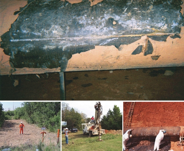
Top: A disbonded, peeling coating on a buried pipeline. Photo courtesy of Jeffrey Didas. Above left: A DCVG survey is performed on a gas pipeline. Photo courtesy of JW’s Pipeline Integrity Services. Above center: A drilling rig is used for installing distributed anodes. Photo courtesy of Jeffrey Didas. Above right: An aging pipeline is being prepared for recoating. Photo courtesy of Jeffrey Didas.
Top: A disbonded, peeling coating on a buried pipeline. Photo courtesy of Jeffrey Didas. Above left: A DCVG survey is performed on a gas pipeline. Photo courtesy of JW’s Pipeline Integrity Services. Above center: A drilling rig is used for installing distributed anodes. Photo courtesy of Jeffrey Didas. Above right: An aging pipeline is being prepared for recoating. Photo courtesy of Jeffrey Didas.

Starting in the 1920s, pipeline operators determined that coatings alone would not provide complete corrosion protection and began installing cathodic protection (CP) systems to enhance the corrosion protection of their pipelines. A CP system applied in conjunction with a coating can also extend the service life of the coating. Typically this pipeline coating will be a dielectric coating, which is a barrier to the flow of electricity. A coating with higher dielectric strength—the voltage required to cause the coating to break down (which is expressed as V or kV per unit of thickness)—will provide superior isolation. The purpose of a dielectric coating is to isolate the pipeline electrically and physically from the environment, while reducing protective current demands on the CP system. Other properties necessary in a dielectric coating are resistance to environmental fluids and the product being transported, impact/abrasion resistance, adhesion, and resistance to cathodic disbondment.

As pipeline coatings age they start to lose their protective properties, such as elasticity and dielectric strength, and will crack or disbond, Didas explains. He comments that an increase over time in CP current requirements to cathodically protect the pipeline is a sign that a coating is deteriorating.

Evaluating a Pipeline Coating

Typically, pipeline operators conduct an “on/off” close-interval potential survey4 (CIS or CIPS) of a pipeline about once every five years to assess the performance of installed CP systems vs. system performance criteria. A CIS can also be used to detect some coating defects.The principle of a CIS is to record the pipe-to-soil (P/S) potential (voltage) profile of a pipeline over its entire length by measuring the potential difference between the buried pipe and surrounding soil—with the CP current sources “on” as well as a synchronized interruption of the CP current sources (“off”)—at test point intervals that do not significantly exceed the depth of the pipe (often ~1 m). Measurements are taken while walking along the length of the pipeline. Didas notes that locations where there is little or no polarization of the pipe indicate the coating may be deteriorating, which can be seen by a downward (less negative) trend of potentials over time that require increased CP current to bring them back to a protective level. Areas where the coating appears to be failing can be further tested using additional aboveground techniques.

The downward potential trend, Didas says, usually prompts the operator to perform a direct current voltage gradient (DCVG) or alternating current voltage gradient (ACVG) test—aboveground methods of measuring the change in electrical voltage gradient (the voltage per unit length along a conductive path) in the soil along and around a pipeline to locate coating holidays and characterize corrosion activity.5DCVG and ACVG surveys evaluate in detail the coating condition on buried pipelines and identify and classify coating holidays. They are performed in those areas where the CIS indicates additional CP is needed.

With the CP system operating at its normal output, the DCVG technique applies a DC signal to the pipeline. Any defects in the coating will allow electric current to flow into the pipe from the surrounding soil. These currents cause voltage gradients in the soil above the pipeline, which can be measured using a voltmeter. Voltage gradients between two reference electrodes placed a distance apart are a result of current pickup or discharge at defect locations in the pipeline’s coating. DCVG surveys are capable of distinguishing between isolated and continuous coating damage.

A CIS of a pipeline in West Texas is performed by a cathodic protection technician. Photo courtesy of JW’s Pipeline Integrity Services.

A CIS of a pipeline in West Texas is performed by a cathodic protection technician. Photo courtesy of JW’s Pipeline Integrity Services.

Protective coating conductance techniques6 measure the coating conductance (inverse of coating resistance) on sections of underground pipelines and are also used to determine the general condition of the coating. This test method only applies to pipe coated with dielectric coatings. Conductance tests are performed whenever significant changes in P/S potentials and current requirements occur. Specific areas with high conductance values on a given section of pipeline indicate a deteriorated coating. To obtain data for coating conductance calculations, interrupted P/S potentials and pipeline current readings are taken at preselected intervals. Soil resistivity can directly affect coating conductance measurements and should be considered when evaluating a section of a pipeline coating.

Once the location of the coating defect is determined with aboveground techniques, visual and electrical inspection of in-service pipeline coatings can evaluate the condition and performance of an external coating system. These inspections can be conducted at bell holes (excavations shaped like an inverted bell, wide at the top and narrower around the pipeline to be examined) dug for inspection purposes. Many operators will also run an inline inspection with a smart tool to determine if there is corrosion where aboveground tests indicate the coating has deteriorated. “If you have a coating issue, you want to check out the internal inspection data, too.” Didas says.

Pipeline recoating is a proven method of rehabilitating pipelines with a deteriorated coating. It is considered the best long-term technical option for coating repair, and is required when the coating has failed and will no longer support CP, Didas says. At this point, he explains, the coating has completely lost its dielectric strength and too much CP current is needed to polarize the pipe. When done properly with a high-performance coating system, he says, recoating can increase the pipe’s service life by 50 or more years. When combined with CP, the service life could be extended to 100 years.

Recoating also can be the most expensive option, Didas adds, noting that recoating today can cost anywhere from $125 to $550 per linear ft (0.3048 m). Challenges associated with recoating a pipeline include pipeline excavation and right-of-way (ROW) conditions, which may be rocky, environmentally sensitive, highly populated, or in close proximity to other pipelines; environmental permitting; pipeline operating conditions; time of year (winter/summer); open blasting for surface preparation; handling and disposal of the removed coating; and landowner issues. As recoated areas of the pipeline increase, he notes, CP requirements should be reevaluated as well, since existing CP systems may need to be adjusted or modified for well-coated pipe.

Extending Aging Coating Life with CP

A linear anode is installed near the pipeline. Photo courtesy of Jeffrey Didas.

A linear anode is installed near the pipeline. Photo courtesy of Jeffrey Didas.

When the aging coating is not yet to the point where the pipeline requires recoating, installing a linear or distributed anode system to augment CP is a cost-effective option that provides protection for the pipeline as well as extends its life, says Didas. Typically, for cross-country pipelines, the impressed current CP (ICCP) design installed during construction is a remote anode bed that provides protective current for miles of pipeline. According to NACE member Norm Moriber, chief engineer with Mears Group, Inc. (San Ramon, California) and MP’s technical editor, the distribution of protective current down the pipeline, which is known as attenuation, is dependent on the resistances between the remote anode bed and the target structure’s surface. This causes the current density to decrease as the distance from the remote anode bed increases. When poor coating condition creates a localized area of low P/S resistance, providing adequate protective current to that area can be difficult. Increasing the current from the remote anode bed to keep potentials above criteria, however, can cause interference issues with neighboring pipelines, as well as overprotect areas of the pipeline closer to the anode bed, Didas warns. Also, the original CP design may not support the need for increased current at localized areas along the pipeline, Moriber adds.

A linear anode CP system resolves these problems by configuring the anode bed as a closely coupled structure that parallels the pipeline, Moriber says. “Overall, linear anodes provide a valuable tool for achieving cathodic protection for pipelines with an aging coating or other special requirements,” he comments. A linear anode is a continuous wire anode, typically comprised of a copper or titanium core and a conductive outer layer, and installed in a coke breeze backfill or prepackaged in a porous sleeve filled with coke breeze. The anode facilitates continuous current distribution along the length of the pipe surface, and its low-current output avoids the coating damage that can happen when trying to provide adequate current to distant locations from a localized anode bed, and excessive CP occurs near the current source. Linear anodes are closely coupled electrically with the pipeline, which minimizes current losses to nearby structures, helps eliminate stray current concerns, and also reduces current requirements for the system. Linear anodes can be installed by cable plow, directional drill, trencher, or backhoe and includes the anode and the header cable in the same installation.

A distributed anode system features individual graphite, cast iron, or MMO anodes, in various shapes and sizes, that are located close to the pipeline and spaced along its length (e.g., every 100 ft [30 m]), and interconnected with a header cable. Distributed anodes provide localized high-current output with an average resistance to earth and a high potential gradient. They can be installed by boring or backhoe and require the header cable to be installed between the anodes.

A rectifier provides power for a remote anode groundbed as well as the linear anode and distributed anodes. Photo courtesy of Jeffrey Didas.

A rectifier provides power for a remote anode groundbed as well as the linear anode and distributed anodes. Photo courtesy of Jeffrey Didas.

The primary factor for determining which type of anode system should be used is typically the pipeline’s ROW, says Didas. If plowing, trenching, or directional drilling can be accommodated, then the linear anode is usually the appropriate choice as it is more efficient and provides a uniform current distribution to the pipeline. Distributed anodes are used when ROW conditions allow only single anode installations because of rocky soil, limited easements, etc. The actual evaluation and selection of the CP system, including installation layout, current requirement testing, anode type, and installation method, should be performed by or under the direct supervision of a NACE-certified CP specialist or licensed corrosion engineer. The evaluation will determine whether a linear anode, distributed anode system, or a combination of both can be successfully integrated with the existing coating and recoated areas.

Adding well-designed CP with quality materials can extend the life of a CP system up to 50-plus years, Didas says. CP vs. recoating is a simpler fix and less intrusive on the pipeline ROW in areas where the pipeline coating is still compatible with CP. Considerations for installing additional CP are pipe accessibility, available electrical power, ROW conditions, the length of pipeline to be protected, and cost. A linear anode CP can be installed for ~$15 to $25 per foot for a typical pipeline ROW. The cost can go up to $50 per foot if the ROW has rocky conditions and there is a need for horizontal directional drilling.

Case History

Didas describes a case history where the asphalt enamel coating on a 255-mile (410-km) long U.S. pipeline, applied between 1960 and 1962 at the time of the pipeline’s installation, was reaching the end of its service life. The 32-in (813-mm) diameter pipeline transports refined products. Environmental factors along the pipeline’s ROW—soil stress, clay soil, rocky soil, and severe drought—had caused coating deterioration, disbondment, and failure over 35% of this line. The existing CP system incorporated conventional remote and close-coupled surface anode beds.

The pipeline integrity program called for conducting regular CIS surveys and other tests to monitor the pipeline’s CP potentials. Where survey results indicated possible coating deterioration, the pipeline owner would determine whether it was feasible and more economical to add CP, or if the section of pipeline needed to be placed on the recoating schedule. Didas notes that it is more cost effective to recoat segments of the pipeline as part of a plan rather than to reactively coat a section here or there; however, if there is a corrosion problem, timely mitigation must be implemented. Over a 10-year period, the pipeline was rehabilitated with recoating and CP. High-performance, two-part epoxy with a service life of 50 years was used to recoat 25 miles (40 km) (more than 98 segments) of the pipeline, the total amount of recoating deemed necessary after aboveground surveys and bell hole inspections were done, Didas says.

CP was added as follows: 195 miles (314 km) of linear anodes were installed in areas where the pipeline was responding well to CP and recoating was not necessary. Linear anodes were used because the existing coating had lost some of its properties—mainly attenuation—and the linear anodes were able to supply continuous current along the length of the pipeline segments. Twenty-one remote CP systems were installed perpendicular to the pipeline (with 500 ft [152 m] typically between the pipe and the first anode) in a conventional or surface anode bed configuration, with 20 to 30 anodes spaced 20 to 30 ft (6 to 9 m) apart due to varying soil resistivity, and buried 15 to 25 ft (5 to 8 m) deep. Two deep anode systems were installed where the ROW conditions did not allow the installation of a remote or linear anode bed and/or surface space was restricted due to possible CP interference issues or lack of an easement. Additionally, eight facility CP system upgrades were done with distributed anode systems, and 400 test sites were added. So far, Didas notes, the recoating and CP upgrades have proven to be successful. The entire CP system, in conjunction with the recoating, is 100% effective over the 255 miles of pipeline ROW. The rehabilitation of this pipeline segment is ongoing. Recoating is performed on a two-year cycle and additional linear anode CP is still being installed as the coating ages.

CP augmentation should be the first choice for pipeline rehabilitation if coating deterioration is addressed early enough, Didas says. The use of CP in lieu of recoating is a very cost-effective strategy for ongoing pipeline protection. Pipeline integrity can be restored using CP to supplement deteriorated coatings as well as protect the recoated segments. The engineering/design/evaluation analysis, however, should be done by qualified personnel to ensure the appropriate rehabilitation strategy is selected.

References

1 “The State of the National Pipeline Infrastructure,” U.S. Department of Transportation, https://opsweb.phmsa.dot.gov/pipelineforum/docs/Secretarys%20Infrastructure%20Report_Revised%20per%20PHC_103111.pdf (December 7, 2016).

2 “By-Decade Inventory,” Pipeline Replacement Updates, U.S. Department of Transportation, http://opsweb.phmsa.dot.gov/pipeline_replacement/by_decade_installation.asp(December 7, 2016).

3 “Background,” Pipeline Replacement Updates, U.S. Department of Transportation, http://opsweb.phmsa.dot.gov/pipeline_replacement/by_decade_installation.asp (December 7, 2016).

4 NACE SP0207-2007, “Performing Close-Interval Potential Surveys and DC Surface Potential Gradient Surveys on Buried or Submerged Metallic Pipelines” (Houston, TX: NACE International, 2007).

5 NACE TM0109-2009, “Aboveground Survey Techniques for the Evaluation of Underground Pipeline Coating Condition” (Houston, TX: NACE, 2009).

6 NACE TM0102, “Measurement of Protective Coating Electrical Conductance on Underground Pipelines” (Houston, TX: NACE, 2002).

Corrosion Basics: High-Temperature Corrosion

High-temperature corrosion is a widespread problem at facilities in various industries, including refineries and petrochemical plants.

High-temperature corrosion is a form of corrosion that does not require the presence of a liquid electrolyte. In this corrosion mechanism, metals react directly with gaseous atoms in the atmosphere rather than ions in solution. Sometimes, this type of damage is called “dry corrosion” or “scaling.” The first quantitative analysis to oxidation behavior was made in the early 1920s with the postulation of the parabolic-rate theory of oxidation by Tammann and, independently, by Pilling and Bedworth.

Although temperatures greater than approximately 90 or 150 °C are sometimes considered “high temperature” (e.g., for heated oil pipelines), this article is concerned primarily with temperatures greater than the “red-hot range,” primarily 650 °C and greater.

Alloys often rely upon the oxidation reaction to develop a stable protective scale that resists further corrosion, such as sulfidation, carburization, and other forms of high-temperature attack. In general, the names of the corrosion mechanisms are determined by the dominant corrosion product(s). For example, oxidation (the general term for a variety of reactions) implies oxides, sulfidation indicates sulfides, sulfidation/oxidation indicates a combination of sulfides plus oxides, and carburization indicates carbides.1

Oxidizing environments refer to high-oxygen activities (concentrations) with excess oxygen. Reducing environments are characterized by low-oxygen activities, with no excess oxygen available. Clearly, oxide-scale formation is more limited under such reducing conditions. It is for this reason that reducing industrial environments are generally considered to be more corrosive than the oxidizing variety.

The properties of high-temperature oxide films, such as their thermodynamic stability, ionic-defect structure, and detailed morphology, play a crucial role in determining the oxidation resistance of a metal or alloy in a specific environment. High-temperature corrosion is a widespread problem in various industries, including:

• Refining and petrochemical

• Power generation (nuclear and fossil fuel)

• Aerospace and gas turbine

• Heat treating

• Mineral and metallurgical processing

• Chemical processing

• Automotive

• Pulp and paper

• Waste incineration

Corrosion resistance at high temperatures stems from a combination of two basic factors: thermodynamics, which determines whether a corrosive reaction will proceed, and kinetics, which determines the rate at which the reaction may proceed. The rate of the reaction may be reduced by careful selection of alloying components, such as inclusion of a multivalent metal that can react with a greater number of oxidizing atoms.

The need for a careful study of the properties of a heat-resistant alloy and its behavior in the anticipated environment is of considerable importance in the selection of a suitable alloy for a particular service application. New alloys and non-metallic materials that are continually being made available to industry are making it possible to make better selections and to establish safe working limits within which the material can be expected to give satisfactory performance over a reasonable length of time.

Reference

1 R.C. John, “Compilation and Use of Corrosion Data for Alloys in Various High-Temperature Gases,” CORROSION/99, paper no. 73 (Houston, TX: NACE, 1999).

This article is adapted by MP Technical Editor Norm Moriber from Corrosion Basics—An Introduction, Second Edition, Pierre R. Roberge, ed. (Houston, TX: NACE International, 2006), pp. 217-218.

Maximising pump efficiency through reduced corrosion and erosion

Posted By Paul Boughton

Industrial processes across the globe require pumps to operate reliably and efficiently. The latest pump designs and coating technologies offer significant improvements in the long term performance of industrial pumps. By minimising the effects of corrosion and erosion, users can enhance productivity and reduce running costs

Continued research into the processes that degrade pump performance is being matched by the development of better application techniques for protective coatings.

By gaining a better understanding of both the pumping process and the factors that affect it, end users can make significant improvements in their maintenance strategies.

Cavitation damage should be prevented by changing the pumping system characteristics
Where cavitation is unavoidable, a bespoke coating system should be used.


Affected applications

Almost every industrial process involving liquids will include a pump at some point. From deep sea oil and gas to DNA sequencing, pumps are required to perform a vast range of tasks. However, no matter what the design or the size of the pump, central to every application is reliability and efficiency – minimising down time and running costs is essential to modern industry.

For those working with large industrial pumps, often operating in harsh environmental conditions, maintaining pump performance in the face of a continuous threat from corrosion and erosion can be a particular challenge. With increased knowledge of these processes and the techniques used to tackle them, it is possible to implement a more cost effective pump refurbishment programme.

Corrosion

Corrosion is commonly defined as a chemical reaction between the component surface and the reacting fluid passing through a pump. In general a distinction is drawn between general or uniform corrosion and localised corrosion like pitting and crevice corrosion. Non-stainless materials suffer mainly from uniform corrosion whereas metals forming oxide layers that adhere to and passivate the surface are prone to localised corrosion.

Flow accelerated corrosion

Flow accelerated corrosion (FAC) describes the removal of the protective oxide layer on a metal. The speed of this process is affected by the oxygen content, the flow velocity and, to some extent, the chloride content. The formation of a calcareous layer due to high carbonate hardness of the water reduces or even prevents FAC.

The influence of oxygen can be seen in the following example: Water with an oxygen content of less than 20 ppb (parts per billion) and a flow velocity around 15 m/s will typically see a corrosion rate around 0.01 mm/year. However, increased oxygen content can see the corrosion rate rise to several mm/year, which will present a significant challenge to the process.

Fortunately FAC only poses a real issue for low carbon steels and cast iron. Increasing the chromium content or using stainless steel will largely eliminate the vulnerability to flow accelerated corrosion.

Erosion

Pumps that are used to transfer fluids containing abrasive substances, such as sand, can experience significant levels of erosion, especially in areas with high flow velocities. This can be seen in the oil and gas industry where injection pumps are employed to force water back into the oil field and thus maintain the pressure which is needed to lift the oil to the surface. The entrained sand particles act as an abrasive and the high working pressures only serve to compound the issue.

From a pure design standpoint, pump manufacturers in this field effectively have two options to minimise the erosion:

* Reduce the flow velocities in every part of the pump

or

* Design the pump in such a way that the flow velocities through the close-running clearances are low.

However, in most cases the specifications required for the application will prevent either of these solutions from being implemented. Coatings with high erosion resistance in selected areas of the pump are a proven solution in these applications.

Erosion corrosion

In operating conditions where both erosion and corrosion are present, the degradation mechanism can become very complex and depends on the type of substrate and the fluid chemistry. Corrosion may create oxide layers with low adherence to the substrate which is prone to erosion, or erosion may damage the passive layer, leading to an activation of the surface which accelerates corrosion. In this case surface protection regimes are often the best and sole option.

Cavitation

Most commonly seen on the pump impeller, cavitation is caused by a pressure difference, either on the pump body or the impeller. A sudden pressure drop in the fluid causes the liquid to flash to vapor when the local pressure falls below the saturation pressure for the fluid being pumped. Any vapor bubbles formed by the pressure drop are swept along the impeller vanes by the flow of the fluid. When the bubbles enter a region where the local pressure is greater than saturation pressure, the vapor bubbles abruptly collapse, creating a shockwave that, over time, can cause significant damage to the impeller and/or pump housing.

In most cases it is better to prevent cavitation rather than trying to reduce the effects on the pumping equipment. This is normally achieved by one of the three actions:

* Increase the suction head

* Lower the fluid temperature

* Decrease the Net Positive Suction Head Required (NPSHR)

For situations where cavitation is unavoidable or the pumping system suffers from internal recirculation or excessive turbulence, it may be necessary to review the pump design or minimize the potential for damage using a bespoke coating system.

Appropriate material selection

For pump manufacturers, the key is to mitigate the corrosion problems by using the most appropriate base material in the construction of the pump. For applications where the use of carbon steel or cast iron is preferred due to cost reasons, the corrosion rate can be estimated very accurately. Based on the mutually accepted corrosion rate per year, the service life of the pump can be anticipated and factored into the maintenance costs of the application.

If the expected corrosion rate is not acceptable the pump materials have to be upgraded to stainless steels which leads to higher costs. In cases where this cost increase is prohibitive, the alternative is to use advanced coatings that can be tailored to suit each application.

If stainless steel is selected for an application, the expected service life is much longer, in some cases infinite. However, this is only true as long as the appropriate stainless steel grade has been chosen for the specific application, it has been produced carefully and is used within the agreed fluid specifications. Special care is required as soon as particles are introduced into the fluid.

In this case even stainless steel becomes susceptible to corrosion due to the passive layer being damaged and the base material becoming activated, which then starts to corrode. Normally the passive layer can be re-established, but if the chloride content is too high or the pH level is too low, the material may remain in an active state and the corrosion continues. Another frequent cause of corrosion in stainless steel pumps are stagnant conditions caused by process interruptions or intermittent operation.

A further threat for stainless steel is chlorine, which is used to combat biological growth in the pump or the connected pipelines. Low level concentrations, around 2 ppm, will have little impact on stainless steel, but it is important to understand how and where the chlorine is introduced into the water flow, to avoid spot concentrations that will damage the protective layer.

Unexpected corrosion can easily negate the anticipated improvement in durability of stainless steel compared to the much cheaper carbon steel variant.

Protective coatings

It is important to determine if the application of coatings will actually improve the performance and the service life of the pump in the first instance and if the costs are really lower than a materials upgrade. In most cases pump manufacturers aim to meet the requirements of a process by using the most appropriate materials for the application and use coatings only as back-up solution.

Polymeric coatings like Fusion Bonded Epoxy can be applied to pump components using a fluidized bed or electrostatic coating. They provide a good level of corrosion protection as long as the coating isn’t damaged. As a polymer coating it is limited to low flow conditions and normally used in clean water applications where it may also improve the hydraulic performance by smoothening the pump surfaces.

However, coatings which are appropriate for pipelines may not be suitable for pump applications where the flow velocities are much higher, narrow passages concentrate the flow and moving parts can be difficult to protect. Again, some methods, such as galvanic protection, commonly used in pipework, are largely unsuitable for pumps.

In these cases coatings are applied to specific areas where increased flow rates are expected or at points where impact damage is expected, such as 90 degree bends. A hard layer is usually applied using a spray coating method such as Air Plasma Spraying (APS), or High Velocity Oxygen Fuel (HVOF) – which one will depend on the required coating thickness and composition.

Carbide coatings, which are deposited by using a high velocity oxy-flame, are extremely wear-resistant. Tungsten carbides in combination with cobalt, nickel or cobalt-chrome matrices are used preferably. Thanks to improvements in the powder and the thermal spray processes, the materials combine high wear-resistance and toughness with good corrosion resistance. Thermal spray coatings can be applied to most substrates, but it is a ‘line-of-sight’ process that makes the coating of complex shaped components, such as impellers, difficult.

CVD processes which are used for complex components that are difficult to coat with thermal spray create very hard surface layers, but are conducted at temperatures in excess of 850 °C. These high temperatures limit the selection of possible substrates, because structural changes and partial deformations can take place during the cooling stage.

Not all coatings are the same

The improvements in performance and durability afforded by coating systems have given rise to a large number of businesses offering a coating service. The raw materials and the basic equipment can be acquired relatively easily and used to apply coatings to a range of equipment.

However, the quality of an HVOF coating, for example, depends predominately on the spraying parameters, such as the material temperature, application velocity, application rate and the quality of the equipment used. Coatings such as these take time to apply correctly, which will inevitably impact on the final cost of the refurbishment. However, increasing the deposition rate will increase the stresses within the coating and over time this can cause the coating to degrade and fail prematurely.

The procedures and settings used by companies such as Sulzer and its coating suppliers have been developed over many years; applying extensive knowledge and experience to the process is the only way to improve it. The final procedure for each coating is closely guarded, proprietary information ensuring that every client will receive the same quality of coating across the world.

To illustrate the importance of these procedures, especially in pump applications, consider the process of installing and removing an impeller. In many situations, the impeller is heated to allow it to be installed or removed from the drive shaft. This shrink-fit procedure can cause inappropriate coatings to be damaged during a routine maintenance operation. Sulzer has ensured that its coating technologies can withstand this thermal shock and continue to deliver long-lasting corrosion protection.

Maintaining legacy equipment

Modern coating technology can be applied to legacy equipment as part of a refurbishment program that will extend the service life of a pump. Implementing a new coating as part of a refurbishment project can significantly improve the performance and reliability of existing equipment.

Ultimately, the key to a successful corrosion prevention scheme is to fully understand the application and to use all the available information to determine the most appropriate action. Working closely with experienced materials engineers enables the end user to achieve the most appropriate solution.

For those looking to refurbish an existing asset there are a number of potential improvements that can extend the service life and improve the performance of a pump. If a new pump design is required, there is an opportunity to establish not only the most appropriate base material, but also the best coating system for extended durability.

The future

As coating technologies continue to advance so end users will be able to select bespoke coatings that can be applied during the manufacturing process.

However, even with the most advanced coating, there is a need to develop an application process that can be used to apply the coating to the complex internal surfaces of a cast impeller and volutes.

As such, this remains the ‘holy grail’ of pump design and once this challenge is overcome, the reliability and service life of industrial pumps will be further improved.

Improvements in service intervals means reduced maintenance costs and reduced costs attributed to lost production. Together with improved efficiency, these costs of ownership can be minimised through the appropriate use of base materials, protective coatings and the implementation of better pump design to deliver a comprehensive and cost effective pump solution.

Applying Cathodic Prevention to Electric Transmission Tower Foundations

The galvanostatic pulse method measures corrosion current density and resistivity of the concrete.

 Electric transmission tower foundations have a great impact on the stability and performance of the towers. Without having sound and safe foundations, these structures cannot perform the functions for which they are designed. Reinforcing steel bars (rebar) in concrete foundations for power transmission towers also act as the ground electrodes during current faults.1

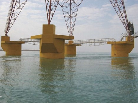
Corrosion assessment, lifetime estimation, and corrosion protection of concrete structures are very important issues in corrosive areas. As an example, Iran operates more than 125,908 km of overhead power transmission and subtransmission lines (>63 kV).2Approximately 19% of these high-voltage lines are located in corrosive coastline environments (Figure 1). Around 17% of these high-voltage lines are more than 30 years old.3 Operation of power transmission lines is controlled by regional electric power companies. One of the companies, Hormozgan Regional Electric Co., spends more than US $400,000 annually to repair and rehabilitate nearly 1,000 corroded tower foundations.4

FIGURE 1: An important sea-crossing mast that transmits electricity to Iran’s biggest island.

FIGURE 1: An important sea-crossing mast that transmits electricity to Iran’s biggest island.

Corrosion and Cathodic Protection of Steel in Concrete

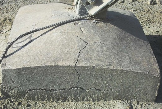
When chlorides reach the steel surfaces inside reinforced concrete structures, active corrosion leads to the formation of expansive corrosion products, resulting in cracks of the concrete cover. It takes only a small amount of corrosion metal loss (e.g., ~0.1 mm) at the rebar surface to create corrosion products sufficient to generate internal stresses that crack the concrete (Figure 2).5

Cathodic protection (CP) is the most effective method of controlling ongoing corrosion in reinforced concrete structures. By applying cathodic polarization, the corrosion potential is shifted to the region of immunity in the Pourbaix diagram; and corrosion is stopped from a practical point of view.6

FIGURE 2: A severely cracked electric distribution tower foundation.

FIGURE 2: A severely cracked electric distribution tower foundation.

The application of CP to a reinforced concrete structure transforms the environment around the steel reinforcement over a period of time. The metal surface becomes negatively polarized, thus repelling chlorides; oxygen and water are consumed; and hydroxyl ions are generated at the metal surface. The hydroxyl alkalinity restores the pH at the metal surface, inducing passivity of the metal.7

Investigations

Evaluations were conducted on 152 selected electric transmission tower foundations located along Persian Gulf coasts. A variety of parameters were measured for corrosion assessment. These parameters included effects of the environmental conditions, as well as the concrete’s structure and properties, on the degree of damage caused by steel corrosion.

During this investigation, NACE SP0308-20088 guidelines were followed. After checking the repair history and visual inspection, data on each foundation were collected for the following parameters:

• Age

• Distance from sea

• Height above the sea level

• Concrete cover depth

• Rebar diameter

• Alkalinity

• Chloride ion concentration

• Concrete homogeneity and compressive strength

• Soil resistivity

• Corrosion potential

• Corrosion current density (CD)

• Concrete electrical resistivity

Alkalinity (pH) and chloride ion concentration were determined from concrete powder obtained by drilling three 30-mm diameter holes, each 25-mm deep. Alkalinity and chloride content values were obtained by averaging the values of three tested samples. According to ASTM C1218-15,9 water-soluble chloride content is used as an applicable parameter related to corrosion occurrence.

The concrete homogeneity and strength were estimated using the Schmidt hammer. The values for cement content and water/cement ratio were obtained from design documents. Since water content in the mix design is a significant parameter affecting structural durability, it was also obtained from design documents and considered in the evaluation.

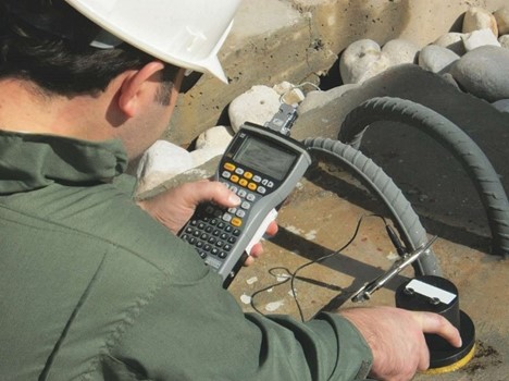
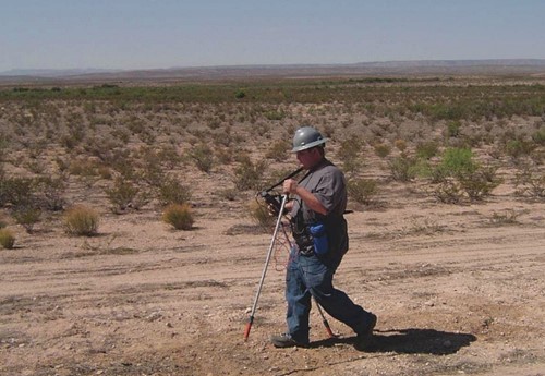
Soil resistivity and corrosion potential were field-measured according to ASTM G57-0610and ASTM C876-09,11 respectively. The galvanostatic pulse method was used to measure corrosion CD and resistivity of the concrete (Figure 3).

FIGURE 3: Galvanostatic pulse measurements determine corrosion potential, corrosion rate, and concrete resistivity.

FIGURE 3: Galvanostatic pulse measurements determine corrosion potential, corrosion rate, and concrete resistivity.

The average temperatures and relative environmental humidity are similar throughout the locations investigated, so the influence of these parameters on the rebar corrosion was not considered.

Results

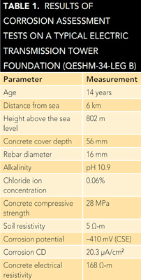
Table 1 shows typical results for one of the selected foundations. The data for each parameter were then analyzed and processed by software developed in-house based on an artificial neural network. This software classified the examined tower foundations into one of four corrosion risk categories (low, medium, high, and very high). The results showed ~60% of the selected foundations were placed in either the high or very high corrosion risk groups.
In addition to using sacrificial anode CP systems with the foundations’ patch repairs, the owner of the high-voltage power lines and towers decided that CP systems would also be used for newly installed foundations, which was the first time this was done in Iran. This type of CP, called cathodic prevention, applies to new structures, which are expected to become contaminated by chlorides during their service life, as well as in-service structures with chloride ions that have not reached the steel and depassivation has not yet occurred. The distinction in these terms relates to the historical practice of applying CP primarily as part of the repair/ retrofit strategy after corrosion has been initiated. Cathodic prevention is a proactive approach.

Applying Cathodic Prevention

Cathodic prevention CD is approximately one order of magnitude lower than the typical requirement for CP. This, in part, is because the steel/concrete potentials required for cathodic prevention are less negative than those required for CP. Furthermore, passive steel is more easily polarized.

For this project, the CD was assumed to be 2 mA/m2 for the steel. Since the surface area of the steel in each foundation is 2 m2, the required current is 4 mA. The necessary weight of the anode material, which includes utilization and efficiency factors, was calculated using Faraday’s law, Equation (1):

W = (ARC * CR * L) / (E * U)           (1)

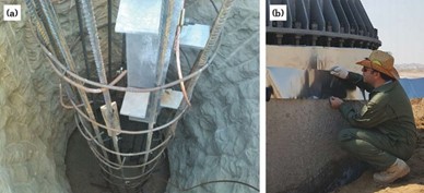
where ARC is the average required current (0.004 A), CR is the consumption rate of the anode (11.2 kg/y for zinc), L is the designed lifetime (20 years), E is efficiency (0.9), and U is the utilization factor (0.85). The calculated weight of zinc is 1,200 g, which is provided by four 300 by 50 by 10 mm discrete galvanic anodes, each containing ~300 g of pure zinc (Figure 4[a]).

The zinc sacrificial anodes were embedded in a chelation material, which forms molecules with the metal ions.

FIGURE 4: Cathodic prevention is applied to the selected foundations (a) by discrete zinc anodes and (b) zinc sheet anodes.

FIGURE 4: Cathodic prevention is applied to the selected foundations (a) by discrete zinc anodes and (b) zinc sheet anodes.

Seventy-two foundations were protected by the cathodic prevention method. To assess performance of systems in the region, cathodic prevention by zinc sheet anodes was also applied on one of the foundations using anodes from the same producer (Figure 4[b]). After one month of operation for the cathodic prevention, the initial performance of the systems was checked according to ISO 12696:2012.12 The results of this evaluation at three different test points indicated that 100-mV potential decay from the instant-off value was achieved within 24 h after opening the circuit.

Conclusions

• The preliminary investigation indicated that roughly 60% of power transmission tower foundations in the north part of the Persian Gulf needed to be protected against chloride-induced corrosion. Hence, CP was the appropriate and logical approach to protect these concrete foundations and prolong their useful lives.

• Cathodic prevention for new foundations was applied using distributed hydrogel and strip-type galvanic systems. After one month of operation, potential decay from the instant-off potential confirmed the effectiveness of the applied system.

Acknowledgements

The authors would like to thank the Hormozgan Regional Electric Co. and Takta Sharif Corrosion Co. for their commercial and financial support. The contribution of Ehssan Gheirati for his review and editing of this article is greatly acknowledged.

References

1 V. Brandenbursky, et al., “Ground Resistance Calculation for Small Concrete Foundations,” Electric Power Systems Research 81 (2011): p. 408.

2 “Electric Power Industry in Iran 2013-2014,” Tavanir Holding Co., report no. 11-11, October 2014.

3 “Statistical Report on 47 Years of Activities of Iran Electric Power Industry,” Tavanir Holding Co., report no. 9-11, October 2014.

4 “Installation of Cathodic Protection System on 5 km Foundations of 230 kV Electric Transmission Line Towers,” Takta Sharif Corrosion Co., report no. 94-084, January 2016.

5 M. Dugarte, “Polarization of Galvanic Point Anodes for Corrosion Prevention in Reinforced Concrete” (Ph.D. diss., University of South Florida, 2010), p. 8.

6 I. Martinez, C. Andrade, “Application of EIS to Cathodically Protected Steel,” Corros. Sci50 (2008): p. 2,948.

7 C. Christodoulou, et al., “Assesssment the Long Term Benefits of Impressed Current Cathodic Protection,” Corros. Sci. 52 (2010): p. 2,671.

8 NACE SP0308-2008, “Inspection Methods for Corrosion Evaluation of Conventionally Reinforced Concrete Structures” (Houston, TX: NACE International, 2008).

9 ASTM C1218-15, “Standard Test Method for Water-Soluble Chloride in Mortar and Concrete” (West Conshohocken, PA: ASTM International, 2015).

10 ASTM G57-06, “Standard Test Method for Field Measurement of Soil Resistivity Using the Wenner Four-Electrode Method” (West Conshohocken, PA: ASTM, 2006).

11 ASTM C876-09, “Standard Test Method for Corrosion Potentials of Uncoated Reinforcing Steel in Concrete” (West Conshohocken, PA: ASTM, 2009).

12 ISO 12696:2012, “Cathodic Protection of Steel in Concrete” (Geneva, Switzerland: ISO, 2012).

Case Histories Internal Corrosion Failures: Are We Learning from the Past?

 In spite of improvements driven by the U.S. Pipeline Safety Improvement Act of 2002 and the added emphasis on integrity management, pipeline failures due to internal corrosion continue to occur. The U.S. Department of Transportation’s Pipeline and Hazardous Materials Safety Administration (PHMSA) recently noted that 206 internal corrosion incidents were reported on regulated gas pipelines between 2002 and 2012, and new regulations are forthcoming that will increase the requirements for internal corrosion management.1 Data published by the Canadian Association of Petroleum Producers (CAPP) showed that the number of internal corrosion incidents per year in Alberta for sweet gas-gathering pipelines went from ~25 in 1985 to 125 in 2008,2 and from ~75 in 1985 to 175 in 2008 for oil effluent pipelines.3

By learning to prevent internal corrosion incidents, operators can reduce operating costs and exposure to business risks. In the recent NACE International IMPACT study,4 the global cost of corrosion was estimated at U.S. $2.5 trillion, with the ability to save from 15 to 35% of this cost using available corrosion-control practices. Pipeline leaks and ruptures resulting from internal corrosion increase risks associated with health, safety, the environment, and deliverability, and can result in regulatory actions and litigation against pipeline operators. This article examines some trends in reported incidents and discusses an analytical methodology based on root cause analysis (RCA) that operators can use to learn from incidents and reduce subsequent or repeated failures.

FIGURE 1: Internal corrosion incidents shown as a percentage of all DOT-reported incident causes for each category, 1994 through 2013.

FIGURE 1: Internal corrosion incidents shown as a percentage of all DOT-reported incident causes for each category, 1994 through 2013.

Internal Corrosion Incidents Continue

Internal corrosion incident data reported to PHMSA by regulated hazardous liquid and natural gas pipeline operators in the United States are available to the public.5 Based on these data, internal corrosion incidents from 1994 through 2013 are shown in Figure 1 as a percentage of all Department of Transportation (DOT) reported incident causes. For this time period, internal corrosion represented 9% of all hazardous liquid incidents, 12% of all gas transmission incidents, and 49% of all gas-gathering incidents.

The number of DOT-reported internal corrosion incidents from 1970 through 2013 for regulated hazardous liquid transportation pipelines and facilities and regulated natural gas pipelines and facilities are shown by decade in Figures 2 and 3, respectively. These figures also show the average number of internal corrosion incidents per year for each decade or time period.

FIGURE 2: DOT-reported serious and significant internal corrosion incidents for regulated hazardous liquid transportation pipelines and facilities from 1970 through 2013.

FIGURE 2: DOT-reported serious and significant internal corrosion incidents for regulated hazardous liquid transportation pipelines and facilities from 1970 through 2013.
FIGURE 3: DOT-reported serious and significant internal corrosion incidents for regulated natural gas pipelines and facilities, 1970 through 2013.

FIGURE 3: DOT-reported serious and significant internal corrosion incidents for regulated natural gas pipelines and facilities, 1970 through 2013.

Generally, the average numbers of internal corrosion incidents reported per year through the 1970s, 1980s, and 1990s were fairly consistent and similar for both hazardous liquid and natural gas pipeline systems. From 2000 through 2009, however, there was a notable increase in the number of internal corrosion incidents on hazardous liquid pipelines. The average number of incidents per year from 2010 through 2013 reached a high of 67, compared to 23 per year for the previous decade. A similar, but lesser trend was observed in the incidents for natural gas pipelines, with an average of 27 incidents per year from 2010 to 2013 vs. an average of 18 incidents per year for the previous decade. Considering that internal corrosion is a time-dependent threat, it is possible that the number of incidents could be increasing in part as a reflection of the aging pipeline infrastructure. This is particularly true if the threat is not effectively identified or mitigated.Figure 4 shows the number of hazardous liquid and natural gas pipeline operators with one or more DOT-reported internal corrosion incidents from 1970 through 2013. These values were determined based on the operator identification number assigned by PHMSA and the number of incidents reported for that operator. A majority of both hazardous liquid and natural gas pipeline operators have reported more than one internal corrosion incident over this period of time. In some cases, operators have reported more than 20 internal corrosion incidents over this 43-year period. These data should be viewed in consideration of the fact that some large operators may operate thousands of miles of pipelines, and the assets owned by each operator are likely to have changed over the years through construction, decommissioning, mergers, acquisitions, and sales. The number of internal corrosion incidents shown in Figure 4 should not be interpreted as being repeat incidents on the same pipelines, although this appears to be true in some cases.

FIGURE 4: Number of operators (both gas and liquid) with one or more DOT-reported internal corrosion incidents, 1970 through 2013.

FIGURE 4: Number of operators (both gas and liquid) with one or more DOT-reported internal corrosion incidents, 1970 through 2013.

From 2004 through 2012, the total number of U.S. hazardous liquid pipeline miles increased by 11%, yet the frequency of internal corrosion incidents in 2012 was nearly three times greater than that in 2004. The total natural gas pipeline miles decreased ~2.5% over the same time period and the incident frequency also declined slightly. The data suggest that increases in total regulated pipeline miles are not a key factor in the increased frequency of internal corrosion incidents.

Learning from Incidents: Three Phases

Analyses performed to determine the causes of an incident can be based on the guidelines of the Systematic Causal Analysis Technique (SCAT) and the loss causation model.6 These tools are commonly used in evaluating safety management systems and process safety incidents. An RCA methodology can be performed in three successive phases following an event. Each phase of the analysis determines different information about the conditions that led to the failure and ways to prevent another incident. The terms “immediate cause,” “basic cause,” and “root cause” are often misused, and each term has a specific meaning as associated with each phase of the incident investigation.

Phase 1: Immediate Cause—Corrosion Mechanism

The first phase of the investigation involves determination of the immediate cause. For an internal corrosion failure, the immediate (or direct) cause of the failure relates to the findings of a metallurgical laboratory analysis performed on the failed pipe section or component. The laboratory analysis is used to determine the damage mechanism that caused the leak or failure. An example of an immediate cause is internal corrosion resulting from high levels of carbon dioxide (CO2) in a wet gas pipeline.

Failure analysis of sections removed from internally corroded pipelines can provide valuable information about the corrosion mechanisms that resulted in a corrosion incident. The corrosion mechanisms responsible for pipeline corrosion may be driven by corrosive gases (e.g., CO2, hydrogen sulfide [H2S], or oxygen [O2]), the presence of water and solid or sludge deposits, biofilms, high velocity or erosion, corrosive chemical species (e.g., acids), or some combination of factors. Laboratory analysis of the corroded pipe, including any liquid and solid samples collected from the pipeline, helps in identifying the chemical, microbiological, and physical conditions that supported the corrosion mechanism. Historical data on pipeline operating conditions, including process upsets, fluid composition monitoring, previous leaks or failures, internal corrosion mitigation measures, etc., are also helpful in interpreting the significance of laboratory test results.

Procedures and other guidance on conducting corrosion failure investigations are available in a number of references.7-8 Sample preservation is one of the most important concerns for obtaining meaningful data from corrosion failure analyses, since corrosion products and microorganisms can change/degrade rapidly upon exposure to air or other contaminants. The main steps in a corrosion failure investigation are listed in Table 1.

Phase 2: Basic Cause—Contributing Factors

The second phase of the investigation involves identification of the basic, or contributing, cause(s) of the failure. Basic causes are factors that contributed to the immediate cause. For example, where the immediate cause of internal corrosion is high CO2 in the gas, the contributing causes may include exceeding the capacity of the upstream gas processing equipment and inadequate corrosion inhibitor injection rates.

A forensic corrosion engineering approach9-10 may be used to understand the contributing causes and underlying mechanisms of the corrosion damage and apply this knowledge to help mitigate future corrosion threats. A fishbone diagram may be used to help evaluate different categories of possible contributing factors, such as people, equipment, measurement, materials, and environment. Often it turns out there is more than one basic cause of an incident, and in some cases a series of cascading events constitute the basic cause.

Phase 3: Root Cause—Management System Factors

True root cause analysis typically leads to a review of management systems to determine why the basic or contributing causes were not mitigated before the incident occurred. Root cause analysis often looks for systemic issues that, if addressed, would prevent a similar incident from occurring in the future. Continuing with the high CO2 gas pipeline example, if a corrosion management system were in place, the organization would have requirements for maintenance planning and procedures, and programs to ensure personnel were trained in those procedures. The management system would also require feedback from gas quality monitoring to ensure that maintenance was being performed correctly and that the gas processing equipment was operating properly.

Many in the oil and gas industry are familiar with pipeline integrity management systems. Standards and regulations on integrity management11-12 identify the management system components that support integrity management activities, such as:

• Policies

• Planning and administration

• Risk evaluation and management

• Compliance assurance

• Project management

• Training and competence

• Communications and data management

• Asset management

• Contractor management and purchasing

• Emergency preparedness

• Learning from events

U.S. Regulations

Discovery of internal corrosion, regardless of whether it affects pipeline integrity, suggests that potentially corrosive species are being (or have been) transported. When corrosion is observed, its cause should be investigated since regulations require operators to take actions to minimize internal corrosion.13 To minimize corrosion, the cause must be known.

PHMSA Advisory Bulletin ADB-08-0814 advises operators of hazardous liquid transmission pipelines to review and analyze numerous factors to determine whether internal corrosion is a threat. The bulletin notes that operators must maintain a detailed record of the analysis to demonstrate the adequacy of corrosion control measures or that corrosion control measures are not necessary. The bulletin also emphasizes the need for operators to periodically reassess the internal corrosion threats to their system and document the results. An internal corrosion health check process for performing and documenting such a review has been proposed.15

Under U.S. pipeline regulations, operators are also required to establish procedures for analyzing accidents and failures, including the selection of samples for laboratory examination, where appropriate, to determine the cause of the failure and to minimize the possibility of a recurrence. The use of the RCA methodology is certainly one way to increase organizational learning by developing a clear understanding of the causes of an incident. PHMSA’s Integrity Management Inspection Protocols for hazardous liquid pipelines specifically mention the need for an effective RCA program and implementation of lessons learned.16 The language in the protocol states that an operator’s RCA program should address:

1. “Rigorous and complete analyses of the problems affecting risk that address the identification of human factors issues, management systems problems, generic component or process failures, positive trends, and system-wide implementation of good practices.”

2. “Rigorous and complete identification of recommendations and corrective actions; and thorough tracking and follow-up of these actions to ensure completion.”

3. “Lessons learned from root cause analysis of incidents developed and distributed to appropriate company employees.”

Conclusions

The RCA methodology provides a tool that operators can employ to increase organizational learning from incidents to reduce the likelihood of repeat incidents. Understanding the significance of immediate causes, basic causes, and root causes will help operators identify and implement appropriate measures to reduce the likelihood of integrity threats such as internal corrosion, and help ensure compliance with U.S. regulations.

References

1 “PHMSA Proposes New Safety Regulations for Natural Gas Transmission Pipelines,” Pipeline and Hazardous Materials Safety Administration, Pipeline Safety Community, March 17, 2016, http://www.phmsa.dot.gov/ pipeline/phmsa-proposes-new-safetyregulations-for-natural-gas-transmissionpipelines (Sep. 14, 2016).

2 “Mitigation of Internal Corrosion in Sweet Gas Gathering Systems,” Canadian Association of Petroleum Producers, publication #2009-0014, June 2009.

3 “Mitigation of Internal Corrosion in Oil Effluent Pipeline Systems,” Canadian Association of Petroleum Producers, publication #2009-0012, June 2009.

4 G. Koch, J. Varney, et al., “International Measures of Prevention, Application and Economics of Corrosion Technologies Study” (Houston, TX: NACE International, 2016).

5 “Pipeline Incident 20 Year Trends,” Pipeline and Hazardous Materials Safety Administration, Pipeline Safety Community, http://www.phmsa.dot.gov/pipeline/library/datastats/pipelineincidenttrends (Sep. 14, 2016).

6 R. Pitblado, M. Fisher, A. Benavides, “Linking Incident Investigation to Risk Assessment,” Beyond Regulatory Compliance, Making Safety Second Nature, Mary Kay O’Connor Process Safety Conference (College Station, TX: Texas A&M Engineering, 2011).

7 ASTM G161-00(2013), “Standard Guide for Corrosion-Related Failure Analysis” (West Conshohocken, PA: ASTM International, 2013).

8 NACE TM0212, “Detection, Testing, and Evaluation of Microbiologically Influenced Corrosion on Internal Surfaces of Pipelines” (Houston, TX: NACE, 2012).

9 J. Gareth, T. Edwards, A. Wright, M. Broadhurst, C. Newton, “Learning Lessons from Forensic Investigations of Corrosion Failures,” Proceedings of the Institution of Civil Engineers—Civil Engineering 162, 5 (2009): pp. 18-24.

10 K.L. Carper, Forensic Engineering, 2nd ed. (Washington, DC: CRC Press, 2001), p. 5.

11 DNV RP-F116 “Integrity Management of Submarine Pipeline Systems” (Oslo, Norway: DNV GL, 2015).

12 ASME B31.8S, “Managing System Integrity of Gas Pipelines” (New York, NY: ASME), p. 9.

13 U.S. Code of Federal Regulations (CFR) Title 49, Part 192.475, “Internal corrosion control: General” (Washington, DC: Office of the Federal Register, 2016).

14 PHMSA-2008-0300, “Pipeline Safety: Proper Identification of Internal Corrosion Risk,” Federal Register 73, 227 (2008): p. 71,089.

15 R. Eckert, “Internal Corrosion Health Check Advised for Liquid and Gas Pipeline Operators,” MP 51, 12 (2012).

16 “Integrity Management Program, 49 CFR 195.452, Integrity Management Inspection Protocols,” Pipelines and Hazardous Materials Safety Administration, August 2013, pp. 8-15.

Battling corrosion to keep solar panels humming

Battling corrosion to keep solar panels humming
February 2, 2017 by Sue Holmes
Battling corrosion to keep solar panels humming
Sandia National Laboratories researchers, left to right, Eric Schindelholz, Olga Lavrova, Rob Sorensen and Erik Spoerke examine points that can corrode on photovoltaic arrays. Sandia researchers collaborate to accelerate corrosion under controlled conditions to help industry develop longer-lasting panels and increase reliability. Credit: Randy Montoya

People think of corrosion as rust on cars or oxidation that blackens silver, but it also harms critical electronics and connections in solar panels, lowering the amount of electricity produced.

 “It’s challenging to predict and even more challenging to design ways to reduce it because it’s highly dependent on material and environmental conditions,” said Eric Schindelholz, a Sandia National Laboratories reliability researcher who studies and how it affects photovoltaic (PV) system performance.

Sandia researchers from different departments collaborate to accelerate corrosion under controlled conditions and use what they learn to help industry develop longer-lasting PV panels and increase reliability. For example, work by Olga Lavrova of Sandia’s Photovoltaic and Distributed Systems Integration department demonstrated, for the first time, a link between corrosion and the risk of arc faults in PV systems’ electrical connections. Research by Erik Spoerke of Sandia’s Electronic, Optical and Nano Materials department focuses on developing new nanocomposite films that could dramatically increase reliability.

“One of our primary goals is to predict how fast corrosion will occur and what damage it does, given certain environments and materials,” Schindelholz said. “This, in turn, gives us information to select the right materials for design or to develop materials for corrosion-resistance for a particular environment. It also allows us to assess the health and operational risk of systems as they age. This is especially important for solar energy systems, which are susceptible to corrosion but are expected to last for decades.”

Corrosion is no small problem. A 2002 study by the National Association of Corrosion Engineers, backed by the Federal Highway Administration, estimated corroding metals in various industries, infrastructure and manufacturing cost $276 billion annually.

Reproducing environmental conditions to study corrosion

Researchers simplify complex environmental conditions in labs to study how materials corrode. It’s not easy deciding which to reproduce.

“Along the coast of Florida, it’s humidity and sea salt in the air. In Albuquerque, we have high ultraviolet (UV) radiation, so UV might be one of the important parameters here. The parameters driving corrosion shift with location and materials,” Schindelholz said. “The challenge lies in identifying the important parameters—and then tuning the knobs in the lab to get something that replicates what we see in an outdoor environment.”

Sandia belongs to a new consortium aimed at speeding up development of new materials for photovoltaic modules, increasing reliability and lowering the cost of solar power-generated electricity. The Durable Module Materials National Lab Consortium (DuraMat) wants to build bridges between the national laboratories and industry so research at the labs can benefit the PV community. DuraMat’s importance is underscored by the fact materials account for about 40 percent of total PV module costs.

DuraMat, led by the National Renewable Energy Laboratory in partnership with Sandia, Lawrence Berkeley National Laboratory and the SLAC National Accelerator Laboratory, will receive about $30 million over five years from the Department of Energy’s (DOE) SunShot Initiative. The consortium is part of the Energy Materials Network, created by the DOE’s Office of Energy Efficiency and Renewable Energy.

Using accelerated aging, forensics to see what’s happening

Lavrova leads projects on the reliability of PV systems, studying how aging affects solar cells and components and how everything performs together. Her team works with Schindelholz on two projects under the SunShot Initiative, a national effort to make solar energy cost-competitive with other forms of electricity by decade’s end. She also contributes to the module durability effort under DuraMat.

One project, in collaboration with the Electric Power Research Institute, studies PV modules from different manufacturers to give the makers information on what kind of degradation they might expect over 30 years to help identify ways to slow it down. Sandia applies accelerated aging principles to speed up studies of slowly developing effects, including corrosion.

The second project, with Case Western Reserve University, studies corrosion and other degradation from a forensic angle—looking back to see what’s already occurred. Lavrova’s team takes a big data analysis approach to study and analyze information from existing installations worldwide. “Is it 1 percent degradation a year or is it 2 percent? Maybe we’ll see some that are a half percent, maybe we’ll see some that are 10 percent. Was it a bad original product or was it installed in Costa Rica where the humidity is 80 percent every day?” she said.

Spoerke’s team wants to block corrosion altogether. Collaborating with Texas A&M professor Jaime Grunlan, the team is developing nanocomposite films made from inexpensive materials as barriers against water vapor and corrosive gases. The team hopes such composite materials, some 100 times thinner than a human hair, will improve ways to protect from corrosion.

Inorganic components and organic polymers that make up thin films must be designed and mixed carefully. “It’s about assembling those structures in the right way so that you can use inexpensive materials and still get the benefits you want,” Spoerke said. “If you build a house, it’s not just piling together the drywall and two-by-fours and shingles. You’ve got to use the two-by-fours to make the frame, set the drywall on the two-by-fours, and assemble the shingles on the roof.”

Thin films aren’t the sole answer, but “I can envision that a technology like the one that we’re developing could be part of a collaborative materials system to help replace glass in next-generation PV applications,” he said.

Systems containing metal subject to corrosion

Sandia has studied corrosion for decades, analyzing the problem in all kinds of systems because anything containing metal is susceptible. Solar cells’ electrical components are protected from corrosion by encapsulating polymers, sealants and glass, but water vapor and corrosive gases can permeate as materials and packaging degrade.

Materials, for example, typically corrode faster in the higher temperatures and humidity of tropical coastal regions than in coastal Antarctica.

Researchers accelerate these real-world conditions in environmental chambers to examine corrosion of electronics and other PV system components. Accelerated tests artificially speed up the corrosion effects of temperature, humidity, pollutants and salt water. For example, salt on icy winter roads or near oceans corrodes cars over time. Since automotive manufacturers can’t wait decades to see how their products resist that, accelerated laboratory tests might spray salt continuously on a surface to qualify coatings and body materials to ensure they’ll be safe and reliable over a product’s lifetime.

Engineers use corrosion chambers to study different materials in systems that must meet particular corrosion requirements, or to expose an electronic component to the environment to see what happens over time.

“Instead of waiting for 30 years of operation outside under the sun, we bring our PV panels inside to expose them to much higher concentrations of light or put them in thermal chambers to simulate the equivalent of years of temperature cycles,” Lavrova said. Accelerated lifetime experiments show in six months what could happen over decades, she said.

Sandia also studies mechanisms underlying corrosion. “That’s a greater challenge,” Schindelholz said. “In we have the chemistry of the atmosphere, the particles landing on surfaces, relative humidity, temperature and so on. We have to understand the interplay of these factors and their interaction with the metal surface.”

Explore further: Accelerated corrosion testing of silver provides clues about performance in atmospheric conditions

Risk Assessment Justifies Cathodic Protection Retrofit on an Aging Pipeline

By Samuel Ojo, Jerry Anietie, Humphrey Ezeifedi, and Mercy Aguye on 12/1/2016 3:05 PM

 As pipelines age, it is important to verify the effectiveness of the coating and cathodic protection (CP) systems that protect them against external corrosion, and implement remedial actions if necessary. To confirm a coating and CP system were still protecting a remote, aging pipeline, an external corrosion risk management assessment was carried out. The assessment included a matrix to determine the likelihood of external corrosion based on coating condition and CP survey data. The ultimate objective was to ensure the adequacy of the pipeline’s CP system.

The 74-km buried carbon steel pipeline was originally installed in 1967 and a section had been replaced in 1990. External corrosion protection consisted of a coal tar enamel coating with an impressed current CP (ICCP) system.

An external coating is the primary corrosion mitigation technique for a pipeline, and a well-applied coating can provide good corrosion protection as the pipeline ages. However, as the coating ages, it can sustain damage from natural deterioration caused by elevated temperatures, stresses, permeation, and biological influences, as well as third-party events. This creates a higher risk for external corrosion of aging pipelines compared to newer pipelines, since the coating is the primary means of corrosion protection. CP is applied to pipelines as a secondary corrosion mitigation method that will protect the pipeline in areas where the coating has defects (holidays) or damage. Coating degradation can cause the CP current requirement for aging pipelines to increase, particularly when the coating has severe damage. In cases where CP current does not provide adequate protection, the risk of external corrosion on the pipeline is even higher, and there is a possibility of a pipe failure.

Risk is generally defined in terms of the possibility or likelihood of failure and consequence of failure. Risk assessment helps to screen for risk, identify areas of potential concern, and develop a prioritized list for more in-depth inspection. Indirect evaluation methods such as CP surveys and coating surveys/condition assessments help determine the likelihood of external corrosion. However, the likelihood of external corrosion should be based on established criteria from both CP and coating rather than only one indirect assessment method, because a combination of CP and coating is used on pipelines to achieve effective external corrosion mitigation.

Historically, due to logistical issues, implementing standard inspections and other integrity assurance activities had been a challenge for the aging pipeline. To assess the likelihood of external corrosion, a simple matrix (Table 1) was developed that combined the outcomes from CP potential surveys and coating condition data. It was designed to account for instances where coating or CP survey data were not available.

The assessment included assumptions about the pipeline’s coating condition. Not only was it susceptible to third-party damage, but the coating’s age (>45 years) also affected its condition. Because coating survey data were unavailable during the pipeline assessment, the coating condition was classified as severe based on the coating survey of a similar pipeline.

Historical CP survey data—pipe-to-soil (P/S) potentials taken at test stations at intervals along a portion of the pipeline (referred to as Section 1) during five years of regular monitoring—were also reviewed. The data indicated that CP protection was adequate, with periods of overprotection and under-protection. Past CP survey data were not available for approximately two-thirds of the pipeline (referred to as Section 2) due to logistical challenges. A CP attenuation study for the entire pipeline helped to predict the behavior of CP potential for the pipeline based on coating quality.

A pipeline coating is expected to electrically insulate the pipe wall, and CP provides corrosion protection at the defects in the coating. Essentially, the current drains or attenuates at the pipe surface where coating defects occur. When only a few coating defects are present, CP current demand is lower and pipeline potential attenuation is slower. Alternatively, CP current demand is higher when more coating defects are present on the pipeline, and the pipeline potential attenuation is faster. Attenuation formulas presented in the NACE International CP-4 Cathodic Protection Specialist course1 were used to develop a CP attenuation curve for the pipeline based on the age of the pipeline coating, current sources for the existing ICCP system, and other assumptions. Since the historical CP potential survey data corroborated the prediction from the attenuation curve for Section 1, the surveyed portion of the pipeline, the attenuation curve was relied on to predict the CP current attenuation for Section 2 of the pipeline that did not have historical CP potential survey data.

FIGURE 1: External corrosion defect data from the ILI were combined with the CP potential survey data results and the attenuation curve. Image courtesy of Samuel Ojo.

FIGURE 1: External corrosion defect data from the ILI were combined with the CP potential survey data results and the attenuation curve. Image courtesy of Samuel Ojo.

The results of the historical CP potential surveys and the attenuation curve for the entire length of the pipeline were plotted. Using the external corrosion risk assessment matrix in Table 1, a significant portion of Section 2 of the pipeline was determined to be at severe risk of external corrosion. To verify the external corrosion risk identified in the assessment, inline inspection (ILI) was used to collect and record information about the pipeline, such as the size, location, and orientation of wall loss (both internal and external) along the entire length of the pipeline. The ILI indicated one significant corrosion defect in Section 1 of the pipeline, and 447 significant corrosion defects in Section 2. The external corrosion defect data from the ILI was combined with the CP potential survey data and the attenuation curve so the direct impact of CP on the corrosion defects along the pipeline could be evaluated (Figure 1). The ILI results corroborated the expectations, indicated by the potential surveys and the attenuation curves, that a portion of Section 2 was experiencing corrosion from inadequate CP. The external corrosion risk assessment and ILI verification justified the need to retrofit the CP system.

To mitigate the corrosion of Section 2, the decision was made to augment the existing ICCP system with magnesium sacrificial anodes as an immediate response while other integrity-related remedial actions were planned to be implemented. CP design calculations indicated that 144 15-kg sacrificial anodes were required to ensure adequate CP on Section 2. Initially, 100 anodes were installed near areas of Section 2 where wall loss was most concentrated, and the remaining 44 anodes were then installed so that Section 2 was fully covered. A subsequent CP survey of the pipeline indicated that the installation of the sacrificial anodes polarized the pipeline to the correct P/S potential so external corrosion growth is minimized and risk is reduced.

This case study3 was presented at the 2016 NACE Corrosion Risk Management Conference. Special thanks to Bademosi Adebayo for his support toward completing this study.

Contacts: Samuel Ojo, Jerry Anietie, Humphrey Ezeifedi, and Mercy Aguye, Shell Petroleum Development Co. of Nigeria—e-mail: samuel.ojo@shell.com.

References

1 NACE CP-4, Cathodic Protection Specialist Course Manual (Houston, TX: NACE International).

2 ANSI/NACE SP0502-2010, “Pipeline External Corrosion Direct Assessment Methodology” (Houston, TX: NACE, 2010).

3 S. Ojo, M. Aguye, H. Ezeifedi, J. Anietie, “Retrofitting the Cathodic Protection System of an Ageing Pipeline,” Corrosion Risk Management Conference, paper no. RISK16-8740 (Houston, TX: NACE, 2016).