Published by Nicholas Woodroof, Digital Assistant Editor
Energy Global, Monday, 19 March 2018 16:26
For pipelines transporting corrosive products, regular monitoring and inspection is vital to ensure long term operation and environmental safety compliance. Recent high-profile pipeline failures have focused increased regulatory scrutiny on the integrity assessment and management of pipeline assets throughout the world. This increase in scrutiny is even more pronounced for pipelines deemed “unpiggable.” When an operator requested an ultrasonic in-line inspection on a pipeline in an environmentally sensitive area, high resolution data provided a complete understanding of the internal condition of their asset, allowing for confident maintenance planning.
History
The inspected pipeline was a sulfuric acid pipeline, located in an environmentally sensitive area. The pipeline had been regularly monitored using hand-held spot ultrasonic (UT) inspection, and had undergone a number of section replacements after several failures, particularly at pipeline bends. Although spot UT can be an effective inspection method, it does not take data measurements of the entire pipeline, but rather takes individual wall thickness measurements at specific intervals along the pipeline surface. Due to the sensitivity of the surrounding environment and corrosive nature of the pipeline product, the performance of an in-line inspection was critical in understanding the full internal condition of the line.
Inspection
There were a number of challenging factors to consider prior to the performance of the in-line inspection. The configuration of the pipeline was such that a number of traditional inspection technologies were not capable of successfully navigating the pipeline. For example, there were numerous 1.0D bends located along the length of the line. For traditional in-line inspection tools, these kinds of navigational features do not allow for the tool to successfully pass through the pipe. It was critical that the in-line inspection tool chosen for this inspection be capable of navigating the challenging configuration of the pipeline. Another component to consider was the pipeline’s liquid product. Since the line carried sulfuric acid, additional actions were taken to ensure the successful inspection of the pipeline. In order to collect accurate data, the tool was contained within a diesel slug with a batch pig, and flowed through the line with 5000 gallons ahead and 10 000 gallons behind, propelled by nitrogen. By using a batching system, the tool was able to both navigate the line and collect high resolution data.
Results
The inspection was successfully performed on the pipeline, and the data was analysed. Interestingly, the data revealed indications of eddy damage near every circumferential weld. These welds were located where newly repaired pipe had been installed. In these areas of newly installed pipe, higher rates of corrosion and erosion were observed. There were also indications of hydrogen grooving adjacent to welds, as seen in Figure 1. However, there were no areas of the pipeline that required immediate remediation.

Figure 1. Inspection data indicating areas of hydrogen grooving along the internal surface of the pipeline.
It was recommended that the areas of deeper weld penetration undergo frequent monitoring, and suggested inspection intervals were presented to the facility. The pipeline was subsequently inspected multiple times in the following years, using ultrasonic in-line inspection. The data from each inspection run was then compared, in order to comprehensively monitor corrosion rates. By performing recurring run comparisons, the rate of any damage occurring on the line could be quantified on a regular basis. Run comparison analyses are largely effective in providing an accurate guideline for future maintenance planning.
Conclusion
By performing repeatable and regular in-line inspections on the pipeline over the course of its lifetime, the operator was able to gauge the complete condition of the asset, identifying localized areas of erosion/corrosion and eliminating the problematic failures that have historically impacted this particular asset. The comprehensive inspection strategy ultimately provided assurance that the asset would continue to operate efficiently, achieving considerable cost savings and peace of mind.
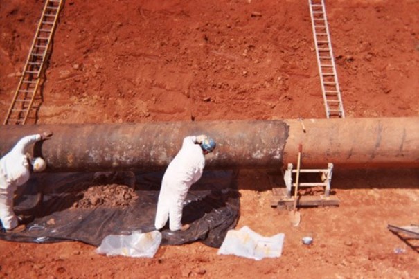 An aging pipeline is being prepared for recoating. Photo courtesy of Jeffrey Didas.