Coupons for Cathodic Protection Evaluation of Mixed-Metal Piping Systems

Coupons can be used to assist in the evaluation of CP levels in buried steel piping.

The measurement and interpretation of cathodic protection (CP) data in plants or other complex facilities present inherent challenges where mixed metals are electrically continuous within the protected structures’ CP system. Often there is no attempt to electrically isolate the buried steel piping networks from other metals in the facility for safety and practical considerations. Coupons can be used to assist in the evaluation of CP levels on buried steel piping in mixed-metal circuits; however, the present industry practice of disconnecting the coupon from the mixed-metal circuit to measure the potential and polarization, without other considerations, raises concerns because the instant disconnect condition may not be a true representation of the protection status.

Although coupon usage has long been recognized as a valuable tool for evaluating CP conditions on buried piping systems, their use in plants and other complex facilities can increase confusion and raise additional questions on the CP status. Plant facilities frequently include extensive buried networks of bare conductors, including copper, steel-in-concrete, mixed-metal circuits, different fill materials, and protected buried structures that are within the influence of closely coupled impressed current anodes. These and other factors present inherent challenges with regard to CP measurements and the interpretation of data.

Depending on the complexity and nature of the facility and equipment, establishing and maintaining electrical isolation can be impractical on networks of steel piping systems within plants. Safety and practical considerations are the key reasons for avoiding electrical isolation devices in classified areas, including the possibility for arcing, reducing touch voltage hazards, and minimizing the propensity for CP downtime, since the failure of a single isolation device in a system can result in complete loss of protection. In critical double containment piping systems, where fabrication requires 100% welded construction, mechanical fittings often are not permitted. In these situations, the CP system is designed to account for the mixed-metal circuit, often using closely coupled impressed current anodes that are distributed throughout the piping network.

When coupons are used in this type of system, the coupon is also within the zone of influence of the anode gradients. Coupon size and placement are critical for collecting meaningful data. The coupon size is selected to match the surface area of a typical coating holiday that is anticipated at a specific location, and proper coupon placement can reduce voltage drop errors. It is also important that the coupon be exposed to the same local environment (including any select fill or controlled density fill) that is in contact with the pipe steel at coating holiday(s). Accordingly, it is essential to collect data at sufficient locations so they are representative of conditions throughout the facility.

Coupons are commonly used when the CP current sources cannot be interrupted; thus, the “current applied—coupon disconnected” (Vc-a-d) is frequently the accepted measurement. However, the voltage drop (sometimes called IR drop) in the measurement can be significant when the coupon is located within the gradient of closely coupled anode systems. Further, the disconnected coupon potential may not be representative of the normal piping condition in a mixed-metal circuit. When it is possible to interrupt the impressed current CP sources for buried piping, coupon “on” and “off” potentials can be measured while connected and disconnected.

The literature on coupons is extensive; however, many questions arise on their proper use when evaluating the CP status of buried piping in a mixed-metal circuit:

• Is the coupon instant-disconnect potential measurement an accurate representation?

• How can the 100 mV polarization CP criterion be used to satisfy NACE International SP0169-2013?1

• Is it appropriate to leave the CP system energized during the coupon instant-disconnect potential measurement?

• How can coupon current measurements be used to evaluate CP status?

• Are other CP criteria appropriate for the location?

Instant-Disconnect Potential Measurements

NACE SP0104-2014,2 Section 3.11, discusses the use of coupons in complex piping environments where mixed metals are electrically continuous with the protected piping. NACE Publication 352013 also addresses the use of coupons in detail, stating that the application of polarized potential or polarization criteria is not always technically correct, and during current interruption, secondary voltage drops from circulating galvanic currents can cause errors in the measurements on structures with characteristic potentials that can vary widely. A suggested approach is to acquire these measurements while locally disconnecting the coupon from the structure. The question remains whether the disconnected coupon’s potential measurement is a true representation of the actual mixed-metal circuit condition.

Simultaneous interruption of all connections between the carbon steel (CS) piping and the bare copper grounding conductors (not a realistic concept) would not be a valid representation of the CS piping condition when in the mixed-metal circuit. The pipe-to-soil potential would be expected to become more negative when the more noble metal (i.e., copper) is disconnected. Depending on the level of polarization of the mixed-metal circuit, similar behavior can be seen on a coupon when it is disconnected.

Figure 1 is a plot of coupon-to-soil potentials in a mixed-metal circuit that includes bare copper grounding conductors and a closely coupled anode system. These potentials were measured with the rectifiers cycling on and off, and with the coupon connected and disconnected during the cycle. It includes four coupon-to-electrolyte potentials, as described in NACE SP0104-2014:

• Current applied—coupon connected (Vc-a-c)

• Current applied—coupon disconnected (Vc-a-d)

• Current interrupted—coupon connected (Vc-i-c)

• Current interrupted—coupon disconnected (Vc-i-d)
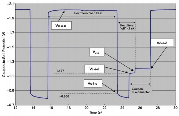
Figure 1 Coupon-to-soil potentials (vs. CSE) in a mixed-metal circuit.

Figure 1 Coupon-to-soil potentials (vs. CSE) in a mixed-metal circuit.

As shown in Figure 1, the potential of a CS coupon can become more negative when it is disconnected from CS piping that remains connected to bare copper. When this behavior is observed, it suggests a greater accuracy concern as compared to the impact of secondary voltage drops from circulating currents during CP current interruption. The Vc-i-c potential represents the coupon’s mixed-metal circuit polarized potential and is considered to be a necessary measurement for CP evaluation. The current applied and interrupted instant-disconnect potentials are also considered to be required measurements. The native and disconnected depolarized potentials are also important.

100 mV Criterion

In complex facilities, the use of alternate protection criteria may be advantageous, including the 100 mV polarization criterion. Correct interpretation in mixed-metal circuits, however, is critical. Simply measuring depolarization from the mixed-metal polarized potential could result in an improper conclusion that CP is effective if this is 100 mV or more. Would this indicate protection if the mixed metal polarized potential is more positive than the open-circuit potential (OCP) of the CS pipe? For example, if the mixed-metal polarized potential is –450 mV in a copper/copper sulfate reference electrode (CSE) and the mixed-metal depolarized potential is –350 mV vs. CSE, can it be concluded that the CS is protected if its OCP is more negative than –450 mV vs. CSE?4

NACE SP0169-2013, Section 6.3.4, states, “In mixed-metal piping systems, CP can be typically achieved at a polarized potential that is 100 mV more negative than the OCP of the most active metal.” Coupons can be used to meet the intent of this standard by showing that the coupon’s mixed-metal polarized potential is 100 mV more negative than the OCP of the coupon.

NACE/ASTM G193-12D5 defines OCP as the corrosion potential—the potential of a corroding surface in an electrolyte measured under open-circuit conditions relative to a reference electrode (also known as electrochemical corrosion potential, free corrosion potential, and OCP). Typically, native potentials are not measured on buried steel piping in plants prior to mechanical completion. Where electrical isolation is not established, native potentials measured after mechanical completion and prior to applying CP are representative of the mixed-metal native state and are not considered to be the OCP of the most active metal. However, a native potential on a coupon can be measured before it is connected to the mixed-metal circuit (after sufficient aging and before initial CP is applied). Upon the application of CP, this measurement provides a baseline to reference the degree of cathodic polarization of the mixed-metal circuit.

After CP has been applied, the depolarized potential often differs from the initial native coupon potential. Subsequent evaluations can identify whether the disconnected coupon depolarizes 100 mV or more positive than the coupon’s mixed-metal polarized potential; or, by allowing the coupon to fully depolarize, reestablish its OCP for comparison to the coupon’s mixed-metal polarized potential. If the fully depolarized disconnected coupon potential is desired, the CP system may have to be de-energized for a prolonged time period where coupons are in the zone of influence of closely coupled anodes. The CP system for CS piping in mixed-metallic circuits as described here should continue to be energized to the greatest extent possible to avoid accelerated corrosion at coating defects on the piping because of the galvanic couple to a massive cathode (i.e., bare copper grounding network).

Voltage Drop

The reference electrode should be located as close to the coupon as is practical, as described in NACE SP0104-2014, to minimize voltage drop error in the potential measurements. A coupon within the zone of influence of an energized anode, as is the case with closely coupled anodes, can show influence from the CP system regardless of whether the coupon is connected or disconnected. SP0104-2014 recognizes that current-applied coupon potential measurements can include voltage drop error. In this standard, “Appendix D, Coupon IR-Drop Calculation Procedure” provides a method to identify voltage drop error.

The most common measurements are Vc-a-c and Vc-a-d. According to NACE SP0104-2014, in mixed-metal circuits, and where the voltage drop may be significant, Vc-i-c and Vc-i-d also should be measured. The difference between Vc-a-d and Vc-i-d is the coupon voltage drop (Vc-IR).

Potential Measurement Evaluation

In Figure 1, Vc-a-d and Vc-i-d are more negative than the Vc-i-c (i.e., the mixed-metal polarized potential). In this case, Vc-i-d is 277 mV more negative than Vc-i-c and, therefore, not considered an accurate representation of the CS condition in the mixed-metal circuit. The same concern applies for the Vc-a-d measurement. Vc-IR is ~–50 mV, which represents the voltage drop error in the Vc-a-d measurement. In Figure 1, Vc-i-c satisfies the polarized –850 mV CP criterion. However, if Vc-i-c was more positive than –850 mV vs. CSE, the 100 mV criterion can be evaluated by comparing Vc-i-c to the OCP of the coupon. The coupon’s native potential that was established before it was connected to the mixed-metal circuit can be referenced as the OCP for evaluating the degree of polarization during the initial application of CP. While this value also could be used for subsequent evaluations in the mixed-metal circuit case, it is recognized that the depolarized potential can differ from the native potential after CP has been applied. Using the native potential is usually preferable to de-energizing the CP system for a long duration that is sometimes necessary to measure the fully depolarized potential.

Coupon Current

A shunt with a known resistance can be installed in series with a coupon to determine the current magnitude and direction. With the CP system energized, direct current (DC) pickup can provide an important indication of CP effectiveness at that location. Protective current density can be estimated from the surface area of the coupon, however, in mixed-metal circuits with the attempt to satisfy the –850 mV CSE polarized criterion, the observed current densities can be orders of magnitude greater than typical design CP current densities for bare CS. Current discharge from a coupon is an indication that protection is lacking and corrosion may be occurring at that location.

An indication of current pickup during the “off” portion of the rectifier cycle does not necessarily imply that CP is effective, as circulating currents can imply corrosion on the piping at other locations. Currents measured during the off cycle also confirm the caution in NACE SP0104-2014. The difference between the “on” and “off” mV drops across the shunt determines the net current on the coupon. The polarities are important to note in these measurements, as they indicate the direction of current flow.

Conclusions

Coupon size, placement, and environment must be carefully considered to provide data that are representative of structural conditions at a variety of locations throughout a facility.

In mixed-metal circuits, the coupon’s instant-disconnect potential alone might not be representative of the actual mixed-metal condition.

The Vc-i-c potential is considered a required measurement to evaluate protection status in mixed-metal circuits. Measurements should be obtained with the coupon connected and disconnected, and with the current applied and interrupted. Voltage drops can be present in the Vc-a-d measurements, especially in the case of closely coupled anode systems that are common in plants.

The 100 mV CP criterion in mixed-metal circuits, referenced from the Vc-i-c potential and the OCP of the CP coupon, meets the intent of NACE SP0169-2013, Section 6.3.4.

CP response can differ in soils vs. areas backfilled with controlled density fill where longer polarization and depolarization durations may be observed.

CP current pickup during the Vc-a-c condition can suggest effective protection at that location, assuming no sources of foreign interference currents are present.

Coupons should be allowed to age until stable native potentials have been established. Coupons should not be connected to the mixed-metal circuit until their native potential is established, and then only when the CP system is ready to be energized.

Acknowledgments

Acknowledgement is given to my colleagues within the Bechtel organization who provided contributions to this article, especially M. Fang, H. Acuna, and D. Chew.

References

1 NACE SP0169-2013, “Control of External Corrosion on Underground or Submerged Metallic Piping Systems” (Houston, TX: NACE International, 2013).

2 NACE SP0104-2014, “The Use of Coupons for Cathodic Protection Monitoring Applications” (Houston, TX: NACE, 2014).

3 NACE Publication 35201, “Technical Report on the Application and Interpretation of Data from External Coupons Used in the Evaluation of Cathodically Protected Metallic Structures” (Houston, TX: NACE, 2001).

4 W.B. Holtsbaum, “Application and Misapplication of the 100 mV Criterion for Cathodic Protection,” MP 42, 1 (2003): p. 30.

5 NACE/ASTM G193-12D, “Standard Terminology and Acronyms Relating to Corrosion” (Houston, TX: NACE, 2013).

This article is based on CORROSION 2017 paper no. 8824, presented in New Orleans, Louisiana, USA.
Corrosion Management and Cost Optimization

By Ali Morshed on 6/1/2017 11:57 AM

Improvement in the optimization of corrosion costs can boost the financial bottom line for many oil and gas assets.
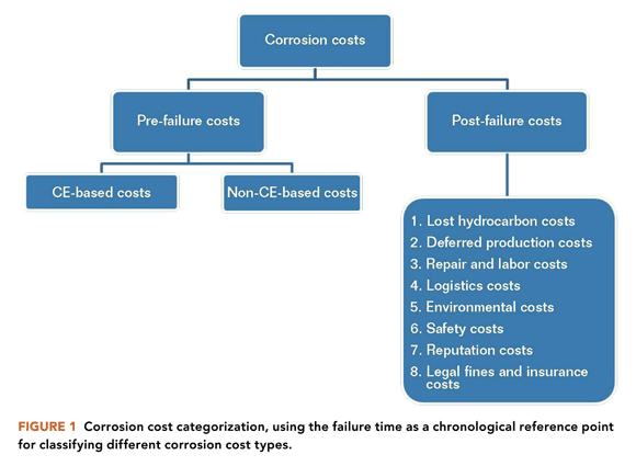
Optimizing corrosion costs can markedly affect the overall integrity management costs for many oil and gas assets. Corrosion costs can be divided into pre-failure and post-failure categories. Preventing corrosion failures to the extent possible will eliminate or minimize post-failure corrosion costs. On the other hand, pre-failure corrosion costs may be further divided into corrosion engineering (CE)-based and non-CE-based costs.

The definition offered herein for the concept of corrosion cost optimization renders it almost fully congruous with the corrosion management concept. That means proper and timely corrosion management applications could facilitate corrosion failure preemption, while simultaneously optimizing both CE-based and non-CE-based corrosion costs.

Corrosion Cost Categorization

There are many different types of corrosion-related costs and different ways of simultaneously classifying or categorizing them. In this approach, the time to failure during an asset’s operation phase is used as a chronological reference point for corrosion cost categorization, as illustrated in Figure 1. Therefore, based on this methodology, there are two main types of corrosion costs: pre-failure and post-failure.

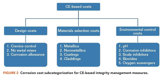
The pre-failure corrosion costs are further divided into CE-based and non-CE-based costs, which pertain to the corresponding integrity management measures. CE-based costs are divided into three smaller subcategories, as illustrated in Figure 2. Some CE-based costs in these subcategories are closely associated with an asset’s design stage (e.g., corrosion allowance and materials selection costs), while others are largely determined during the design stage and materialize during the asset’s operation stage (e.g., corrosion inhibitor and biocide injection costs).

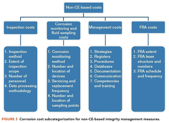
Non-CE based corrosion costs are divided into the following four subcategories:

• Inspection costs

• Corrosion monitoring and fluid sampling costs

• Management costs (e.g., producing or updating strategies, procedures, databases, various documentation, communication, and the corrosion management strategy document)

• Failure risk assessment (FRA) activities costs

Figure 3 illustrates those parameters or variables which influence the four non-CE-based costs.

Post-failure corrosion costs include, but are not limited to:

• Lost hydrocarbon and deferred production costs

• Repair and labor costs

• Reputation costs

Once the different types of corrosion costs are fully identified—their origins together with the variables that determine and influence their magnitude, extent, and duration—planning can begin for optimizing these costs. Such corrosion cost optimization must be accomplished without sacrificing the performance and efficiency of any of the asset’s incumbent or future CE-based or non-CE-based integrity management measures.

Cost Optimization Definition

After clearly defining and understanding the various components of the corrosion-related costs, corrosion cost optimization can be defined as managing the cost of both CE-based and non-CE-based integrity management measures in such a way that corrosion failures are kept to a minimum (ideally zero) while the efficiency and performance of these measures are not sacrificed, compromised, or adversely affected.

The following points could be further highlighted with regard to the above definition:

• By preventing corrosion failures or minimizing the number of their occurrences as much as possible, a significant portion of corrosion costs (Figure 1) can be avoided, thereby markedly reducing the overall corrosion cost figure.

• Not all corrosion costs pertain to an asset’s operation phase; a significant portion is associated with the design phase. Hence, a proper design process could play a major positive role in optimizing the overall corrosion costs.

• By definition,1 corrosion management incorporates both CE-based and non-CE-based integrity management measures exactly as corrosion cost optimization does. Therefore, thorough implementation of corrosion management applications can significantly affect and optimize overall corrosion costs.

Corrosion Management and Cost Optimization

A comparison of the corrosion management concept1 and corrosion cost optimization reveals marked congruity between the two. Both concepts incorporate components such as CE-based and non-CE-based integrity management measures. Thus, such similarity means that adequate and proper corrosion management implementation can influence both CE-based and non-CE-based measures in such a way that the extent and effectiveness of these measures are not compromised, yet potential corrosion failures are preempted as much as possible (i.e., the near total elimination of the post-failure corrosion costs), and pre-failure corrosion costs are also optimized.

Eliminating the post-failure corrosion costs (via preempting potential corrosion failures) is achieved through proper application of CE-based and non-CE-based integrity management measures, which themselves are best optimized through proper corrosion management implementation. The following two sections describe in more detail how such corrosion management implementation can enhance both CE-based and non-CE-based integrity management measures and simultaneously optimize their pertinent costs, thereby optimizing the overall corrosion costs.

Optimizing Corrosion Engineering-Based Costs

CE-based costs are divided into the following three subcategories:

• Design costs (e.g., corrosion allowance)

• Materials selection costs (e.g., metallic and non-metallic options)

• Environmental control costs (e.g., corrosion inhibitor injection)

The variables listed under each subcategory (Figure 2) determine the total cost associated with that subcategory and contribute to the overall CE-based cost.

A very important point is highlighted here regarding the upstream hydrocarbon assets and their associated pipelines. The costs associated with these three CE-based subcategories are very much dependent on conducting proper well sampling and the accuracy of sample analyses during an asset’s design stage. Any erroneous conclusions regarding the corrosivity level of the produced fluids can have huge adverse repercussions. Conclusions that fluid corrosivity is greater than is actually the case can increase design-stage costs when implementing the following:

• Specifying thicker corrosion allowances

• Selecting corrosion-resistant alloys (CRAs), which are typically more expensive than carbon steel

• Including inner coatings or claddings instead of, or in addition to, corrosion inhibitor injection for internal protection of equipment

• Injecting higher-than-necessary concentrations of various chemicals (e.g., corrosion inhibitors)

Thus, opting for such overdesign options, due to erroneous fluid sampling and/or compositional analysis, could have a huge adverse effect on the overall CE-based costs at the design stage. Some components of such overdesign options at the design stage (e.g., overdosed chemical treatment) could also continue well into an asset’s operation stage before (if at all) they are rectified.

Furthermore, asset underdesign based on sampling/analyses errors may appear to have optimized corrosion costs at the design stage; however, such assets can suffer from the following corrosion costs post-commissioning:

• Increased CE-based costs such as material replacements or corrosion allowance upgrades along with injection of higher doses of chemicals to control or reduce an increasing number of corrosion failures due to an underdesign

• Increased post-failure corrosion costs due to inadequate corrosion control measures that result in earlier and more frequent failures than expected in an asset’s life

The best way to optimize CE-based corrosion costs is to avoid both overdesigned and underdesigned corrosion control measures, while requiring that fluid sampling and analyses are carried out in an accurate and meticulous manner.

It is of paramount importance to remember that CE-based cost optimization commences at the design stage and continues throughout the operation stage. Any revisions, alterations, or variations in the incumbent corrosion measures during the operating stage will directly influence the overall CE-based corrosion costs.

Optimizing Non-Corrosion Engineering-Based Costs

As illustrated in Figure 3, non-CE-based corrosion costs are divided into four subcategories that are associated with different integrity management measures. The cost optimization pertaining to each measure is discussed individually.

Inspection-Related Costs

Inspection-related costs are best optimized if the inspection scope is fully risk-based. A conservative inspection scope can mean unnecessary inspection costs. Conversely, a scope that is not risk-based and has fewer selected points (compared to a risk-based scope) may not detect high-risk or high-corrosion-rate areas. That means there is a greater likelihood of failure and the occurrence of post-failure corrosion costs.

Corrosion Monitoring and Fluid Sampling Costs

This situation is exactly the same as inspection-related costs. A conservative approach to corrosion monitoring and fluid sampling creates unnecessary costs. On the other hand, a less conservative approach increases the chance that higher corrosion rates are not detected, which can possibly lead to failures and their associated post-failure corrosion costs.

Management Costs

Many costly corrosion failures are related to inadequate or totally absent items such as registers, databases, communication, and competency (Figure 3). Furthermore, their creation (if they do not already exist) or updating can be done often at little or no cost. Producing and updating such items can significantly improve corrosion management of an asset and preempt corrosion failures. Simultaneously, pertinent corrosion costs can be significantly optimized.

Failure Risk Assessment Costs

The only cost associated with FRA activities is the cost of carrying them out. Therefore, proper planning and ensuring that the FRA process is carried out using reliable input will optimize such activities and thus their pertinent costs.

Cost Optimization Misconceptions and Their Repercussions

The greatest corrosion cost misconception is to reduce a CE-based and/or non-CE-based integrity management measure without assessing the possible adverse effects it may have on the overall corrosion control program. That is, the integrity situation in the long term can actually deteriorate when downsizing or reducing the inspection scope, chemical injection rate, training budget, communication, etc., without carrying out any prior assessment to determine the effect of such reductions in size, number, rate, or budget. The fact is, in many observed cases, an instant decision is made to reduce a particular CE-based or non-CE-based integrity measure in a way to make a cost saving. However, such improper and superficial acts often lead to much greater corrosion costs in the long term.

Conclusions and Recommendations

Conclusions

Preempting corrosion failures would eliminate post-failure corrosion costs, thus significantly reducing the overall corrosion costs.

Due to the congruity between the concepts of corrosion management and corrosion cost optimization, proper implementation of the former can have a marked positive influence on the latter.

Recommendations

Beginning at the design stage, avoid both overdesign and underdesign in corrosion engineering as much as possible. Basing engineering decisions on accurately collected information is critical to achieving this objective.

Pay close attention to the management requirements (within the non-CE-based category). Proper and timely creation of such requirements, including their regular updating and maintenance, can significantly improve corrosion management implementation, and significantly optimize non-CE-based costs.

References

1. A. Morshed, The Evolution of the Corrosion Management Concept, MP 52, 8 (2013), p. 66

Guide Helps Estimate Cost and Service Life for Protective Coatings

By Materials Performance on 6/29/2017 3:23 PM

The guide’s purpose is to present a practical, easy-to-use document to identify, compare, and select protective coating systems that are cost-effective for specific environments.

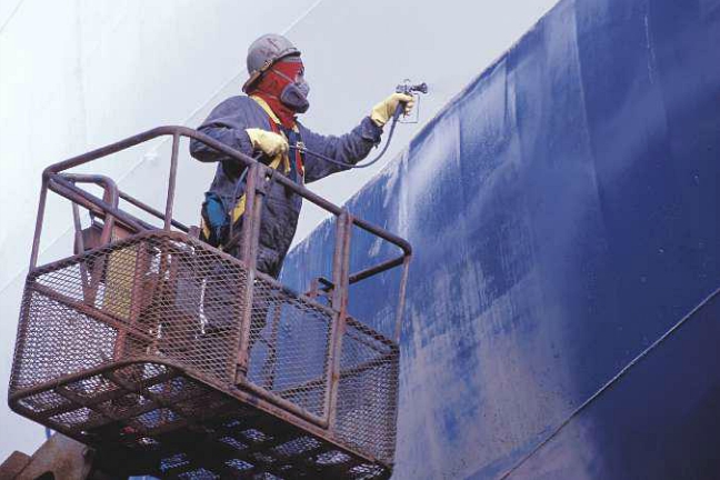
To help coatings engineers or specifiers determine candidate protective coating systems for particular industrial environments, NACE International members Jason Helsel and Robert Lanterman developed a practical guide, “Expected Service Life and Cost Considerations for Maintenance and New Construction Protective Coating Work” (CORROSION 2016 paper no. 7422). This guide discusses commonly used generic coating systems and the service life for each in specific environments; current costs for materials and their application (both shop- and field-applied); and guidelines for calculating installed system costs. The authors comment that specific job costs will vary depending on the characteristics of a project, and note that the guide’s purpose is to present a practical, easy-to-use document to identify, compare, and select protective coating systems that are cost-effective for specific environments.

To identify the costs of surface preparation, coating application, and materials for typical industrial environments, as well as the available generic coatings used in those environments and the expected service lives of those coatings, a survey was implemented to collect information from major protective coatings manufacturers, steel fabricators, painting contractors, and end users. Cost data were developed from collected data as well as common industry cost references.

The authors use a “practical life” maintenance approach in the guide for projecting the life of the coating system, which estimates the service life as the number of years before first maintenance painting should begin—when the coating exhibits 5 to 10% breakdown and active rusting of the substrate is present—rather than the time until a coating system needs to be replaced.

Data tables in the guide for the estimated practical service life of coating systems include information such as generic coating types (i.e., acrylic, alkyd, epoxy, epoxy phenolic, epoxy zinc, organic zinc, inorganic zinc, metalizing, moisture curing polyurethane, and miscellaneous coatings); types of surface preparation—hand or power tool cleaning or abrasive blast cleaning; number of coats; and minimum dry film thickness (DFT) of the coating. Coating types are grouped into categories for either atmospheric exposure or immersion (water) service. Coating life-expectancy information corresponds to the corrosivity of the service environments. The harshness of atmospheric service is classified as C2 through C5 for mild, moderate, severe (heavy industrial), and seacoast heavy industrial, as defined in ISO 12944-2, “Classification of Environments.” The service environments corresponding to immersion service include potable, fresh, and salt water immersion.

Generally, the authors say, most users follow a maintenance painting sequence of spot touch-up and repair, then maintenance repaint (spot prime and full coat), and finally full repaint (total coating removal and replacement). They estimate the number of years for a practical maintenance sequence as follows: spot touch-up and repair at the practical life (P) of the coating system, maintenance repainting at the coating system’s practical life plus 33% (P x 1.33), and full repaint at the coating’s practical life plus 50% (P x 1.5).

Helsel and Lanterman emphasize that distribution of coating breakdown must also be taken into account when judging the costs and feasibility of maintenance painting. “For example, 5% breakdown that occurs in well-defined areas can be practically repaired through localized touch-up, whereas 5% breakdown uniformly scattered across 100% of the surface may be beyond practical spot repair,” they say.

Also, the authors point out that the practical maintenance sequence may not always represent the most economical approach to maintenance painting. The physical characteristics of the existing coating and the amount of corrosion present are the determining factors, and it may be possible to perform several touch-up and maintenance repainting cycles and push the time until full repainting is required. They note that the decision to conduct a maintenance repaint vs. a full repaint should be based on results of a coating investigation that assesses coating thickness, adhesion, substrate condition, and the extent and distribution of corrosion.

The guide also presents a data table with the estimated material cost per square foot for particular paints/protective coatings based on a typical DFT for that coating. Coatings listed include various acrylics, alkyds, epoxies, polyurethanes, siloxanes, zinc-rich coatings, and others.

Additionally, data tables are presented for non-material costs for shop painting and field painting, which include costs per square foot for surface preparation, application labor for various types of shop coatings (one-pack products, two-pack epoxies and urethanes, zinc-rich primers, and plural component spray) and field coatings (one-pack brush/roller and spray, two-pack spray epoxies and urethanes, spray zinc-rich primes, and plural component spray); equipment; and other related costs. The authors comment that the practical life of the coating and the cost of the repainting steps will vary depending upon whether the original coating was applied in the shop or in the field and provide an example of cost estimates for a typical maintenance painting sequence for both shop-applied and field-applied original coatings.

To compare the costs of one coating system to another, Helsel and Lanterman comment that the time table for maintenance painting, the number of maintenance painting cycles required to achieve the structure’s desired life, and the cost of these painting operations at current cost as well as net present value and net future value, should be noted. The guide provides several calculations to determine net present value and net future value, along with examples. With this information, the cost of a coating system for long-term protection over the structure’s life can be determined, which gives the user a comparable basis for selecting a coating system.

Soil-Side Corrosion Causes Premature Failure of Oil Storage Tank Bottom Plates

By Materials Performance on 6/29/2017 3:25 PM

Soil side of the failed plate sample.

Arefinery was experiencing bottom plate underside (soil-side) corrosion of its aboveground storage tanks (ASTs) at an extraordinarily high rate of 1 to 2 mm/y, which resulted in the failure of four tanks within a two-year period that occurred seven years after the refinery was commissioned. All four tanks had severely damaged bottom plates, which were constructed of 8-mm thick uncoated carbon steel.

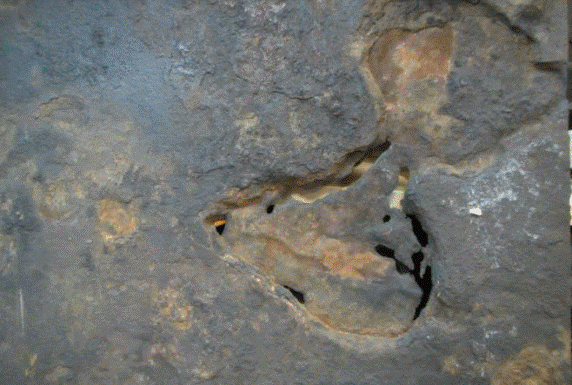
Underside corrosion protection for the ASTs was provided by an impressed current cathodic protection (ICCP) system using a mixed-metal oxide (MMO) grid anode system. The corrosion morphology after the failure revealed severe localized corrosion with large, deep pits found under deposits of orange-red tubercles comprised of iron oxides.

In CORROSION 2017 paper no. 9025, “Premature Failure of API 650 Oil Storage Tank Bottom Plates Due to Soil Side Corrosion,” authors N. Al Abri, J.R Nair, A. Al Ghafri, and F. Al Mawali describe the failure analysis carried out, which included a review of the design and function of the CP system and metallurgical tests of a failed bottom plate sample.

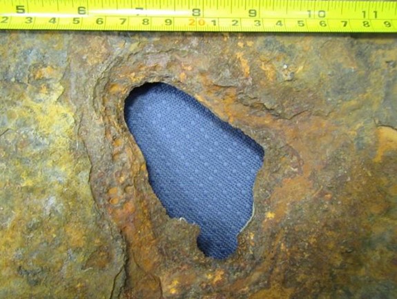
A 100-by-100 mm hole was observed when layers of metal were removed from the sample’s soil side.

A 100-by-100 mm hole was observed when layers of metal were removed from the sample’s soil side.

For the ICCP system, the MMO anode grid was placed between a high-density polyethylene (HDPE) secondary containment liner and the tank bottom, which sat on a 75-mm thick sand pad. The underside of the bottom plates was uncoated and the CP design was based on 100% bare surface area.

The failures occurred between July 2013 and August 2015, and a detailed CP survey was carried out for the storage tanks in February 2016. The results revealed that none of the tanks achieved the NACE SP0193-20161 protection criterion of –850 mV instant “off” potential. The potentials varied from –200 to –800 mV vs. a copper/copper sulfate (Cu/CuSO4) electrode (CSE), with an average “off” potential of –450 mV vs. CSE across all tanks.

Since the potentials were not meeting the –850 mV criteria, further investigation was done to understand the possible reasons for such low polarized potentials. The authors note that design deficiencies of the ICCP system—primarily the anode depth/spacing and inappropriate distribution of power feed cables—resulted in a nonuniform potential profile across the tank bottom surface. High current and voltage attenuation along the anode grid did not provide sufficient current and polarization at a distance away from the power feeds, which led to under-protection of the tank bottom.

Because an inefficient CP system alone typically doesn’t cause such aggravated corrosion, a sample from the failed tank bottom was sent to an external laboratory for a detailed metallurgical analysis to identify corrosion products and possible corrosion mechanisms. A form of underdeposit corrosion (UDC) that can corrode steel at the rate of 1 mm/year is microbiologically influenced corrosion (MIC).

Multiple perforations were seen under the corrosion deposits.

Multiple perforations were seen under the corrosion deposits.

X-ray diffraction analysis of the sample plates’ soil side indicated the tubercles were made of porous layers or strata consisting mainly of iron oxides surrounded by magnetite (Fe3O4). The scales appeared to consist of multiple layers. A closer analysis performed on flakes from scale on the pits indicated the probability of iron-oxidizing bacteria (IOB) present in the corrosion, which formed deposits that further aggravated the corrosion by forming a differential aeration cell. IOB produce orange-red tubercles of iron oxides and hydroxides by oxidizing ferrous ions from the bulk medium or the substratum.2

The corrosion rates observed were amplified by the ingress of water, primarily from leaking fire water sprinklers, through gaps between the annular plate and foundation, which brought in bacteria and corrosive anions such as chlorides and sulfates. Without an effective CP system and no other means of corrosion control, the tank floor was exposed to a severe form of bacterial and UDC that led to perforation and loss of inventory.

References

1 NACE SP0193-2016 (formerly RP0193-2001), “External Cathodic Protection of On-Grade Carbon Steel Storage Tank Bottoms” (Houston, TX: NACE, 2016).

2 A.W. Peabody, Peabody’s Control of Pipeline Corrosion, 2nd ed., R. Bianchetti, ed. (Houston, TX: NACE International, 2001), p. 279-280.