New Tantalum Alloy Resists Highly Corrosive Environments

By Paul Aimone on 8/31/2017 1:39 PM

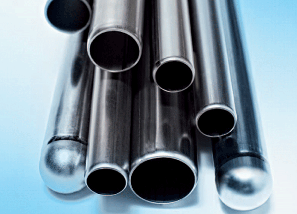
Tantalum Tubing for Chemical Processing. Photo courtesy of H.C. Starck.

Tantalum and tantalum alloys have been used in electronic, chemical processing, and other industries for many years. The largest single use of tantalum is as a powder in capacitors. The tantalum oxide film that forms on tantalum serves as a dielectric. Mill products also comprise a very significant market for tantalum and tantalum alloys. Tantalum mill products such as plate, sheet, foil, tube, rod, and wire are extensively used in the chemical, pharmaceutical, electronic, semiconductor, medical, aerospace, and tooling industries. Tantalum mill products are, for the most part, produced by a combination of ingot metallurgy and thermomechanical processing regardless of the product’s final form.

Pure tantalum and tantalum alloys have excellent corrosion resistance1 and are used in chemical processing and pharmaceutical equipment where hot, highly corrosive environments are encountered. Heat exchangers, liners, feed lances, rupture disks, and various other components are fabricated from these materials. Tantalum and tantalum alloys are resistant to most acids (one exception is hydrofluoric acid [HF]) in a wide range of concentrations and temperatures and exhibit corrosion resistance that is similar to glass; and are often the material of choice when other alloys would rapidly corrode and fail in service.

Tantalum’s excellent corrosion resistance results from the formation of an extremely stable tantalum pentoxide (Ta2O5) layer.2 In temperatures ranging from 190 to 250 °C, however, the Ta2O5 layer can degrade, depending on the process environment, and allow rapid chemical attack of the component. In the presence of hot, hydrogen-containing acids, diffusion of atomic hydrogen along grain boundaries can lead to hydrogen embrittlement (HE).2 Rather than metal loss from corrosion, HE is the predominant failure mechanism for tantalum components in the chemical processing industry. Carbon, hydrogen, nitrogen, and oxygen begin to significantly embrittle tantalum at individual concentrations of 100, 100, 1,000, and 1,000 ppm, respectively.

Operational Limits of Tantalum Material in CPI

Tantalum and tantalum alloys are used almost exclusively in processes that require extremely hot, concentrated hydrochloric acid (HCl) or sulfuric acid (H2SO4). Temperature limits for tantalum in HCl and H2SO4 to minimize corrosion rates (5 mpy [127 µm/y]) are shown in Table 1.

As these temperature limits are approached and exceeded, corrosion and rapid HE can occur. Presently cathodic protection using small platinum spots affixed to the surface of a tantalum component is the most prevalent method used for slowing HE in tantalum alloys. Over time, however, these spots dissolve and need to be replaced.

Previous studies demonstrated that platinum spotting improved the corrosion and HE resistance of pure tantalum, although the effect was almost insignificant for the tantalum-tungsten alloy Ta-3W.3 Consequently, H.C. Starck (Newton, Massachusetts) successfully developed a derivative of the Ta-3W alloy that incorporates platinum-group elements such as platinum or ruthenium, which significantly improved the alloy’s corrosion and HE resistance.1 This new alloy maintains the same physical, mechanical, and fabrication properties as the original Ta-3W alloy.

Figures 1 through 4 show the results from corrosion evaluations of the new platinum-containing Ta-3W alloy in 30% HCl and 96% H2SO4.4 Test specimens, measuring ~1 by 1.5 by 0.02 in (25 by 38 by 0.5 mm), were cleaned, weighed, and measured prior to testing. Individual test specimens were fully immersed in an acid solution. Conventional Ta-3W samples were tested as a baseline along with the new alloys. The samples were separated from each other using polytetrafluoroethylene (PTFE) spacers. All tests, except for the samples immersed in HCl, were performed in conventional plastic labware. The HCl tests were performed in specialized, PTFE-lined pressure vessels. After the tests were completed, each sample was rinsed and dried. Corrosion rate evaluations were performed based on weight change. Localized corrosion attack was evaluated by visual examination at 20x. The corrosion rate (mpy) was calculated based on the weight-change data. Hydrogen enrichment was determined by wet chemistry techniques where the sample was dissolved in acid and then analyzed.

When exposed to 30% HCl acid at 220 °C for 15 weeks, the corrosion rate of the Ta-3W alloy with platinum was reduced (Figure 1), although this rate is already low. Hydrogen enrichment (embrittlement) dropped by more than 100 times compared to the conventional Ta-3W alloy with or without platinum spots (Figure 2). In Figures 1 and 2, the data points at 0 ppm retained concentration represent the test results for conventional Ta-3W.
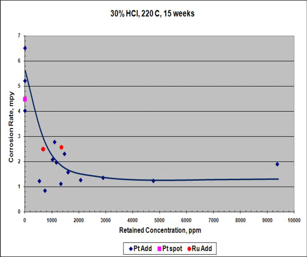
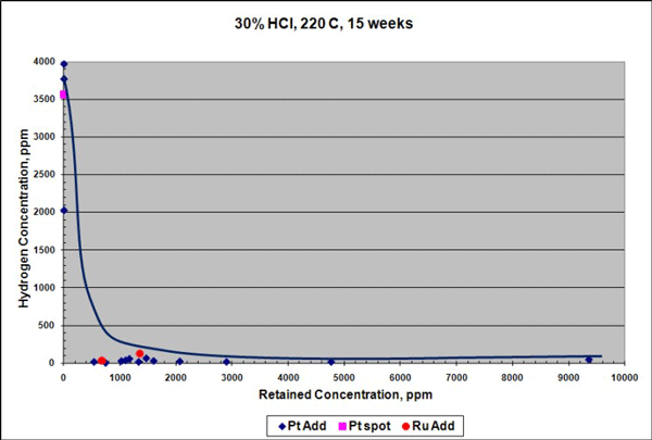
FIGURE 1: Corrosion rate for Pt-modified Ta-3W in 30% HCl.

FIGURE 1: Corrosion rate for Pt-modified Ta-3W in 30% HCl.
FIGURE 2: Hydrogen enrichment for Pt-modified Ta-3W in 30% HCl.

FIGURE 2: Hydrogen enrichment for Pt-modified Ta-3W in 30% HCl.

Similar results were seen for samples exposed to 96% H2SO4 at 230 °C for 15 weeks, although the reduction in corrosion rate in H2SO4 was not as pronounced as in HCl. Platinum additions reduced the corrosion rate of the Ta-3W alloy up to 3 times (Figure 3), and there was no measurable hydrogen enrichment at this temperature, as shown in Figure 4. Raising the temperature to 250 °C increased the corrosion rate of the platinum-containing alloy to ~7 mpy (178 µm/y), but with no measurable hydrogen enrichment. It is theorized that platinum improves corrosion and HE resistance in tantalum by producing low hydrogen overvoltage sites within the alloy that shift its electrical potential in a more noble, positive direction. This would help stabilize and preserve the protective Ta2O5surface oxide film.
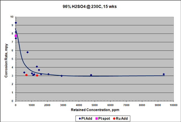
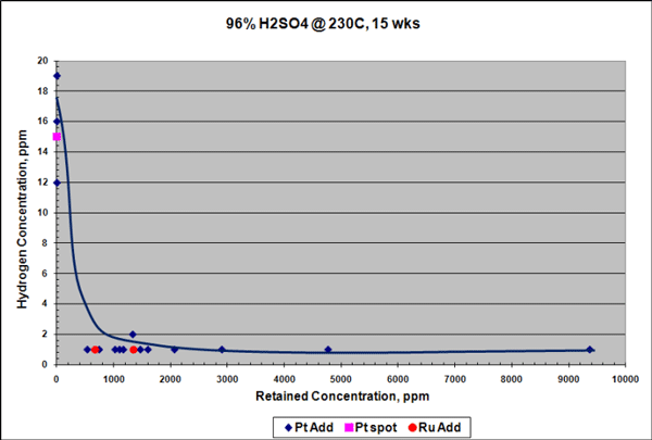
FIGURE 3: Corrosion rate for Pt-modified Ta-3W in 96% H<sub>2</sub>SO<sub>4</sub>.

FIGURE 3: Corrosion rate for Pt-modified Ta-3W in 96% H2SO4.
FIGURE 4: Hydrogen enrichment for Pt-modified Ta-3W in 96% H<sub>2</sub>SO<sub>4</sub>.

FIGURE 4: Hydrogen enrichment for Pt-modified Ta-3W in 96% H2SO4.

While platinum additions clearly improve the corrosion performance of the Ta-3W alloy, at the concentration ranges used in the modified alloy described here, there is a significant cost impact associated with this alloying element. Ruthenium has been shown to improve the corrosion performance of titanium alloys by reducing the hydrogen overvoltage in various acid media.5 The results of recently completed trials show that adding low levels of ruthenium also improve the corrosion and hydrogen enrichment resistance of the Ta-3W alloy in both HCl and H2SO4 at high temperatures. More importantly, this improvement in corrosion resistance is achieved in the same concentration ranges (i.e., optimally 1,000 to 3,000 ppm) as the platinum-containing Ta-3W alloy. Since ruthenium is roughly 10% of the cost of platinum at the time this paper was written, a Ta-3W alloy with ruthenium would potentially offer the superior corrosion performance of the Ta-3W alloy with platinum at a significant cost savings.

References

1. P. Aimone, E. Hinshaw, “Tantalum Materials in the CPI for the Next Millennium,” CORROSION 2001, paper no. 01330 (Houston, TX: NACE International, 2001).

2. J. Chelius, “Use of Refractory Metals in Corrosive Environment Service,” Mater. Eng. Quart. Aug (1957): pp. 57-59.

3. E. Rabald, Materials and Corrosion, Vol. 12 (Weinheim Germany: WILEY-VCH Verlag GmbH & Co., 1961), pp. 695-698.

4. P. Aimone, “A New Tantalum Alloy with Improved Corrosion and Hydrogen Embrittlement Resistance,” Proc. 7th Corrosion Solutions Conference, held September 21-23, 2009 (Huntsville, AL: ATI Wah Chang, 2009).

5. R.W. Schutz, “Ruthenium Enhanced Titanium Alloys,” Platinum Metals Rev. 40, 2 (1996): pp. 54-61.
Soil-Side Corrosion Causes Premature Failure of Oil Storage Tank Bottom Plates

By Materials Performance on 6/29/2017 3:25 PM

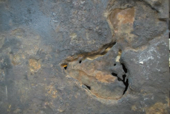
Soil side of the failed plate sample.

Arefinery was experiencing bottom plate underside (soil-side) corrosion of its aboveground storage tanks (ASTs) at an extraordinarily high rate of 1 to 2 mm/y, which resulted in the failure of four tanks within a two-year period that occurred seven years after the refinery was commissioned. All four tanks had severely damaged bottom plates, which were constructed of 8-mm thick uncoated carbon steel.

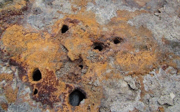
Underside corrosion protection for the ASTs was provided by an impressed current cathodic protection (ICCP) system using a mixed-metal oxide (MMO) grid anode system. The corrosion morphology after the failure revealed severe localized corrosion with large, deep pits found under deposits of orange-red tubercles comprised of iron oxides.

In CORROSION 2017 paper no. 9025, “Premature Failure of API 650 Oil Storage Tank Bottom Plates Due to Soil Side Corrosion,” authors N. Al Abri, J.R Nair, A. Al Ghafri, and F. Al Mawali describe the failure analysis carried out, which included a review of the design and function of the CP system and metallurgical tests of a failed bottom plate sample.

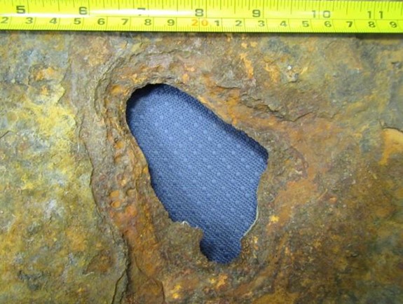
A 100-by-100 mm hole was observed when layers of metal were removed from the sample’s soil side.

A 100-by-100 mm hole was observed when layers of metal were removed from the sample’s soil side.

For the ICCP system, the MMO anode grid was placed between a high-density polyethylene (HDPE) secondary containment liner and the tank bottom, which sat on a 75-mm thick sand pad. The underside of the bottom plates was uncoated and the CP design was based on 100% bare surface area.

The failures occurred between July 2013 and August 2015, and a detailed CP survey was carried out for the storage tanks in February 2016. The results revealed that none of the tanks achieved the NACE SP0193-20161 protection criterion of –850 mV instant “off” potential. The potentials varied from –200 to –800 mV vs. a copper/copper sulfate (Cu/CuSO4) electrode (CSE), with an average “off” potential of –450 mV vs. CSE across all tanks.

Since the potentials were not meeting the –850 mV criteria, further investigation was done to understand the possible reasons for such low polarized potentials. The authors note that design deficiencies of the ICCP system—primarily the anode depth/spacing and inappropriate distribution of power feed cables—resulted in a nonuniform potential profile across the tank bottom surface. High current and voltage attenuation along the anode grid did not provide sufficient current and polarization at a distance away from the power feeds, which led to under-protection of the tank bottom.

Because an inefficient CP system alone typically doesn’t cause such aggravated corrosion, a sample from the failed tank bottom was sent to an external laboratory for a detailed metallurgical analysis to identify corrosion products and possible corrosion mechanisms. A form of underdeposit corrosion (UDC) that can corrode steel at the rate of 1 mm/year is microbiologically influenced corrosion (MIC).

Multiple perforations were seen under the corrosion deposits.

Multiple perforations were seen under the corrosion deposits.

X-ray diffraction analysis of the sample plates’ soil side indicated the tubercles were made of porous layers or strata consisting mainly of iron oxides surrounded by magnetite (Fe3O4). The scales appeared to consist of multiple layers. A closer analysis performed on flakes from scale on the pits indicated the probability of iron-oxidizing bacteria (IOB) present in the corrosion, which formed deposits that further aggravated the corrosion by forming a differential aeration cell. IOB produce orange-red tubercles of iron oxides and hydroxides by oxidizing ferrous ions from the bulk medium or the substratum.2

The corrosion rates observed were amplified by the ingress of water, primarily from leaking fire water sprinklers, through gaps between the annular plate and foundation, which brought in bacteria and corrosive anions such as chlorides and sulfates. Without an effective CP system and no other means of corrosion control, the tank floor was exposed to a severe form of bacterial and UDC that led to perforation and loss of inventory.

References

1 NACE SP0193-2016 (formerly RP0193-2001), “External Cathodic Protection of On-Grade Carbon Steel Storage Tank Bottoms” (Houston, TX: NACE, 2016).

2 A.W. Peabody, Peabody’s Control of Pipeline Corrosion, 2nd ed., R. Bianchetti, ed. (Houston, TX: NACE International, 2001), p. 279-280.

Essential Elements of a Successful Corrosion Management Program

By Ben DuBose on 6/30/2016 3:41 PM (taken from http://www.materialsperformance.com/articles/material-selection-design/2016/07/essential-elements-of-a-successful-corrosion-management-program)

betchel

Maintaining an effective corrosion management program is essential for achieving high reliability at any oil and gas production or refining facility, according to project officials from industry contractor Bechtel.

Sameer V. Ghalsasi , a NACE International member and materials specialist at Bechtel Oil, Gas and Chemicals in Houston, Texas,  explained the most important elements of such a program in a presentation1 at the recent NACE Corrosion Risk Management Conference, held May 23-25 in Houston, Texas.

“An effective corrosion management program is necessary for successful operations,” Ghalsasi says. “This process starts as early as the conceptual design phase, and it continues throughout the design life of the facility.”

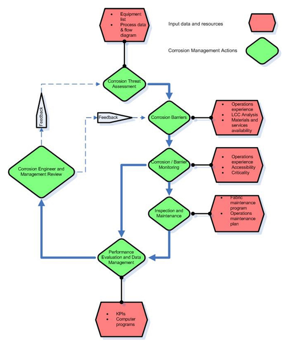
FIGURE 1: This is a sample corrosion management strategy used in a recent case at a water treatment facility. Photo courtesy of Bechtel.

FIGURE 1: This is a sample corrosion management strategy used in a recent case at a water treatment facility. Photo courtesy of Bechtel.

Identification of Corrosion Threats

In the early stages of development, a comprehensive list of all probable corrosion threats should be compiled. From there, each threat is evaluated based on process conditions, past experience, industry standards, and simulation models, if available.

For example, Ghalsasi reports that in a recent case involving a water treatment facility (Figure 1), the most probable corrosion threats to the plant were identified early in the process as carbon dioxide (CO2) corrosion, external atmospheric corrosion, and microbiologically influenced corrosion (MIC).

The determination of those threats is much simpler for brownfield projects, or expansions of existing facilities. This is because historic data are available from the operations team for that facility, and exact information about site conditions is also available.

“The operations team’s past experience plays a vital role in determining the credible threats and the mitigation measures,” Ghalsasi says. Meanwhile, identifying the threats for a greenfield project—or new facility—is more challenging. This is because only a limited amount of process data are available, and it becomes even more difficult to predict variations in the process parameters during future startup and shutdown periods, during upset conditions, and during future chemical injections.

“In those situations, the corrosion assessments are usually based upon past experience or experimental results,” Ghalsasi says.

Life-Cycle Cost Analysis

Once credible corrosion threats are identified, the next step in the process is to determine the feasibility of using low-cost construction materials—such as carbon steel (CS). This life-cycle cost analysis provides the means to assess the viability of CS.

The total cost analysis for using CS should include capital expenditures such as the costs for materials, fabrication, quality control, logistics, and procurement; operational expenditures like monitoring, inspection, maintenance, repair, materials and chemicals supply, training, and management costs; and the cost of failure. The costs of failure would include any loss of production or materials, as well as the costs of repair and punitive costs due to personnel and environmental safety incidents.

A similar analysis can also be made for considering a suitable corrosion-resistant alloy or a non-metallic material.

Looking at recent cases, Bechtel found that the most suitable construction material could vary based on the objective of the particular process unit. For large diameter pipelines that cover long distances and are designed for limited service life, CS can be economical, even with the high operating cost due to corrosion management and maintenance.

However, for pipelines that are relatively smaller and cover shorter distances, the initial savings in capital expenditures from using CS are surpassed by the operational expenditures over the service life. In that situation, using a corrosion-resistant alloy has proven to be more economical over the long run, Ghalsasi says.

Corrosion Control Strategies

Once the analysis is completed, the next step in the process of developing a corrosion management strategy is to determine the corrosion control technologies to be used. Numerous industry standards provide guidelines for the threat assessment and control selection.

One control strategy often implemented in oil and gas facilities is material selection. Depending on the predicted corrosion mechanisms, materials and/or heat treatments are chosen. Additionally, expected corrosion rates are calculated for the projected life of the unit, and a suitable corrosion allowance is selected for the service life.

Another oft-used solution can be external coatings, like paint. This is the primary defense mechanism for atmospheric corrosion. The coatings require normal maintenance, including touch-up of any damaged areas and possibly a full repainting  every 10 to 15  years to ensure that the protection is maintained.

Similarly, linings are effective barriers for internal corrosion due to process fluid. These internal linings often require special application processes and equipment, and they are normally suitable for large tanks and vessels. Meanwhile, cladding with a corrosion-resistant alloy can be a solution when maintenance of other internal linings is not practical.

Coating is often selected in conjunction with cathodic protection (CP), which can be used on buried or immersed metallic components and structures.  Sacrificial anode (passive) and impressed current (active) are two popular techniques of CP, Ghalsasi says.

Other solutions include corrosion inhibitors and chemical injection. Within the inhibitors, neutralizing inhibitors and filming corrosion inhibitors comprise the most popular categories. Neutralizing inhibitors control the pH of the process fluid, while filming corrosion inhibitors form a protective barrier on metal surfaces.

“Inhibitor selection is perhaps the most critical step in the development of a successful corrosion inhibition program,” Ghalsasi says.

Some factors considered in inhibitor selection are the uninhibited corrosion rate, wall shear stress, temperature, the total dissolved solids, the solubility of the inhibitor in water, the inhibitor’s compatibility with other production chemicals and with handling and storage materials, and environmental regulations.

The final inhibitor selection then typically involves laboratory or field testing.

“Focusing solely on the efficiency of a corrosion inhibitor is not sufficient,” Ghalsasi says. “The availability of the inhibitor plays an equally important role in corrosion management. The inhibitor availability also takes into account any practical limitations in the deployment of a corrosion inhibitor into the system.”

Meanwhile, various types of chemicals can also be injected to reduce the corrosion rate, including biocides and oxygen scavengers. However, some chemicals may promote undesired corrosion effects if used improperly.

“In order to avoid undesirable effects, a chemical injection program is almost always coupled with a monitoring and inspection program,” Ghalsasi says. “For petroleum refineries, NACE SP01142 provides guidelines for the location, design, performance verification, and the monitoring of the injection and process mix points.”

Corrosion Monitoring and Inspection

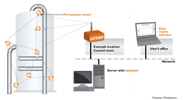
FIGURE 2: A corrosion monitoring system is one of many online methods now being used to combat corrosion. Photo courtesy of Permasense.

FIGURE 2: A corrosion monitoring system is one of many online methods now being used to combat corrosion. Photo courtesy of Permasense.

Once corrosion threats and the respective controls are identified, the next step in management is to select proper monitoring and inspection techniques to determine the effectiveness of the deployed barriers. Some barriers are active and require constant surveillance or monitoring, while routine inspection may be adequate for other barriers.

Depending on the technique used, corrosion monitoring can detect corrosion while it is happening, whereas inspection reveals the end effects of corrosion that have already taken place.

“Both techniques are essential for a successful corrosion management program, and they allow corrosion engineers to take the necessary actions to prevent future corrosion losses,” Ghalsasi says.

Some of the most common monitoring techniques include online methods such as mass loss coupons, electrical resistance (ER) probes, linear polarization resistance (LPR) probes, and hydrogen probes. A new technology involving the use of online UT measurements and data transfer through a wireless router can provide high precision rate measurements, allowing trouble to be addressed before too much material has been lost (Figure 2).

Additionally, sampling stations are sometimes provided at key locations in the process facility. With sampling stations, the extracted process fluid can then be further analyzed for electrochemical properties—which, in turn, can give a greater understanding of the corrosion characteristics of the process fluid.

“This type of monitoring is offline monitoring,” Ghalsasi says of the sampling stations. “While it allows greater flexibility and reliability, it does require more time.”

Meanwhile, some of the commonly used inspection techniques are visual inspection, radiographic testing (RT), ultrasound testing (UT), eddy current testing (ECT), magnetic particle testing (MT), and liquid penetrant testing (PT).

Program Performance Review and Management

The final step in Bechtel’s suggested process is the program performance review, which involves receiving feedback on the reporting and analysis of measurements obtained from chemical injection, corrosion monitoring, and inspection. This step also acts as the interface between the corrosion engineering team, operations team, and facility management.

“Hence, the information reported should be meaningful to all interested parties,” Ghalsasi says.

“Apart from communicating the technical details such as inhibitor qualities, corrosion rates, and wall thickness measurements, it is equally essential to talk in terms of cost, man-hours, and schedule,” he adds.

Ghalsasi also noted that several key performance indicators (KPIs), such as the availability of corrosion inhibitors, could assist in the effective reporting of information obtained in the corrosion management program. One example is a cost of corrosion KPI, where the corrosion damage sustained during a monitoring cycle is converted into an equivalent dollar value. Another is an equipment maintenance completed KPI, which measures the percentage of maintenance activities completed in a given cycle.

“Communication with facility operations staff plays a vital role in the development of this strategy,” Ghalsasi says. “Historic data and past experience obtained from the facility are of paramount importance in this process.”

The information reported in terms of KPIs is then reviewed and analyzed in order to take any necessary corrective actions.

“The types of corrosion threats and their controlling techniques can vary largely depending on the nature of the facility, its location, and the degree of criticality of a system, piece of equipment, and/or associated piping,” Ghalsasi says.

“There is no single flowchart or one procedure that can cover all the requirements,” he adds. “However, these components can form a central theme for a successful corrosion management program.”

Contact Sameer V. Ghalsasi, Bechtel—e-mail: svghalsa@bechtel.com.

References

1 S. Ghalsasi, B. Fultz, R. Colwell, “Primary Constituents of a Successful Corrosion Management Program,” NACE Corrosion Risk Management Conference, paper no. RISK16-8734 (Houston, TX: NACE International, 2016).

2 NACE SP0114-2014, “Refinery Injection and Process Mix Points” (Houston, TX: NACE, 2014).