Corrosion-Resistant Thermal Spray Coatings Withstand Supercritical CO2 Environments

By Kathy Riggs Larsen on 10/31/2016 3:33 PM

Carbon capture and storage (CCS) is a carbon sequestration method that minimizes the release of carbon dioxide (CO2) into the atmosphere when burning carbon-based fuels. Primarily, CCS involves capturing the CO2emissions from fossil fuels used in electricity generation and industrial processes, separating it from some other gases if needed, compressing it, and then transporting and injecting it into a storage site such as depleted oil and gas wells or saline aquifers to ensure long-term isolation from the atmosphere. According to the Carbon Capture and Storage Association, CCS technology can capture up to 90% of CO2 emissions.1

Before it will be widely adopted by industry, CCS needs to be proved to be economically viable; however, corrosion issues can arise when separating, transporting, and storing high-pressure, wet CO2, says NACE International member Shiladitya Paul with TWI (Cambridge, United Kingdom). Although the CCS concept is based on a combination of known technologies, he says, large-scale adoption and integration of existing individual technologies poses challenges. Paul notes that corrosion concerns can be different depending on the process stage, and understanding these issues, filling in any technology gaps, and mitigating the corrosion is important for full-scale implementation of CCS as a CO2 emissions reduction tool.

Low-alloy steel and carbon steel (CS) tend to corrode in the presence of wet CO2 due to the formation of carbonic acid (H2CO3). The presence of combustion constituents such as sulfur oxides (SOx), nitrogen oxides (NOx), and other contaminants in the CO2 stream, along with chemicals such as amines used in the CO2 capture process, can form acidic solutions when in contact with water that are corrosive to a variety of metals and alloy systems. In situations where wet hydrogen sulfide (H2S) is present, cracking can be an issue for high-strength steels. If the corrosion rate is too high in these environments, corrosion-resistant alloys (CRAs) may be used. The cost of these materials, though, can be prohibitive.

In his CORROSION 2015 paper no. 5939, “Thermally Sprayed Corrosion Resistant Alloy Coatings on Carbon Steel for Use in Supercritical CO2 Environments,”2 Paul discusses an experiment where the corrosion resistance of CS samples thermally sprayed with various CRA coatings was tested in an environment that recreated conditions that may be found during CO2 transportation and storage. The concept, he explains, combines the corrosion resistance of a CRA coating with the structural integrity of CS as an economical alternative to structural components fabricated of a monolithic CRA for CCS and other applications where supercritical CO2 (CO2 held in a fluid state at or above its critical temperature and pressure) is encountered. If the CRA coating is damaged, it can be repaired and the component reused without costly replacement. Although metals, alloys, and welds have been tested and characterized in low-pressure CO2 and CO2/H2S systems for a number of years, information on their use under higher pressures is limited and test data are needed for materials to be used with confidence in high-pressure applications.

For the experiment, four CRAs were selected—UNS N10276, UNS N06625, UNS S31603, and UNS R50250—that have a proven track record for corrosion resistance in environments similar to the CCS environment or harsher, and are also available in powder form. Generally, CRA refers to a metal that can withstand corrosion in a given environment, Paul says. Three of these CRAs have ≥16% chromium, which enables them to form a thin, tenacious, corrosion-resistant chromium oxide surface layer that protects the substrate from the harsh CO2 and H2S environment. The fourth CRA (UNS R50250) is comprised mainly of titanium, which is known to perform well in corrosive environments. The composition of the metals used is given in Table 1. These metals were thermally sprayed onto the surface of 5-mm thick, 40 by 40 mm square coupons cut from CS (UNS G10200) plate. The metal coating was applied using a high-velocity oxy-fuel (HVOF) thermal spray process. The coatings were nominally 300-µm thick.

The CRA-coated test coupons and an uncoated CS control coupon were exposed for 30 days in an autoclave with a 3.5 wt% sodium chloride (NaCl) solution. The autoclave was heated to 40 °C and the test pressure was raised to 10 MPa by pumping in a mixture of 95% CO2 and 5% H2S. The test was carried out in a deaerated environment to avoid elemental sulfur and oxide rust. For this experiment, the researchers were observing the combined effect of CO2 and H2S under the very high pressure that would be experienced in CCS applications, along with the aggressive environment. “I would expect that if the CRA could survive this environment, it is likely to function fairly well in other CCS environments that one might see; however, one needs to test in the environment envisaged,” comments Paul. After exposure, the specimens were taken out, air dried, and photographed. Photographs of Cr alloy-coated specimens before and after testing are shown in Figure 1.
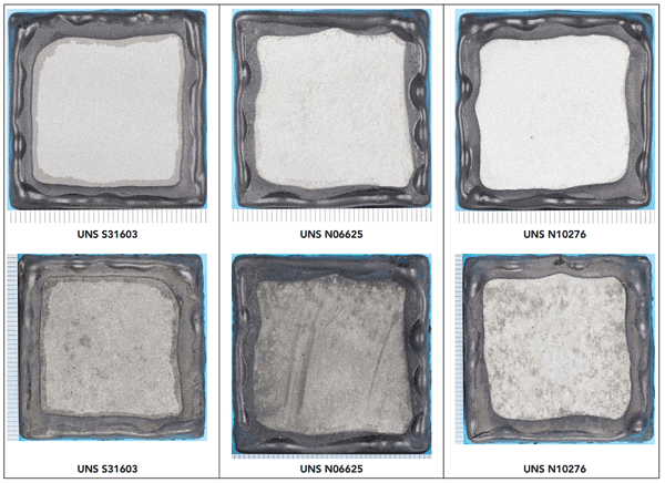
FIGURE 1: Photographs of specimens coated with a chromium-rich CRA before testing (top) and after testing (above). Photos courtesy of Shiladitya Paul.

FIGURE 1: Photographs of specimens coated with a chromium-rich CRA before testing (top) and after testing (above). Photos courtesy of Shiladitya Paul.

A cross-sectional examination was performed and the coupons’ microstructure evaluated to see if the CRA coatings protected the underlying substrate. Microstructural characterization revealed that the bare steel formed a mackinawite (iron sulfide) scale and corroded at a rate of ~0.3 mm/y, while the thermal spray coating layers protected the steel substrate from CO2/H2S corrosion. In all cases, none of the CRA coatings experienced corrosion of the CRA material itself. When sectioned and viewed under a microscope, some porosity was seen in these coatings, which is expected in thermal spray coatings, but very little evidence of corrosion was seen at the coating-substrate interface. Only the titanium coating (UNS R50250) showed some evidence of corrosion at the interface. From micrographs taken of the cross section, it was apparent that the titanium coating had more intersplat porosity than the other coatings, which could explain the formation of some corrosion product at the coating-substrate interface.

Paul explains that in a thermal spray coating process, the consumable (metal powder, wire, or rod) is heated to a molten state. The molten particles are then accelerated toward the component being coated; and when each molten particle hits the substrate at a high velocity, it forms a flat, pancake-shaped deposit called a “splat.” The splats overlap to create a lamellar structure, and intersplat porosity refers to spaces or voids that form between the splats. Some of these pores can be connected and form a pathway for contaminants to reach the substrate and initiate corrosion.

On the titanium-coated sample, the corrosion products were only present at certain locations where through-thickness porosity was present. “What we think happened is the environment—the sodium chloride solution saturated with 95 percent carbon dioxide and 5 percent hydrogen sulfide—entered into the pores and reached the carbon steel, where it started corroding the substrate,” says Paul. Although the titanium material itself is very corrosion resistant, he notes, the barrier performance of the coating depends on the quality of the coating provided by the material.

While it is virtually impossible to achieve a thermal spray coating that is completely free of porosity, he adds, the parameters of the thermal spray process (such as the particle size, spray distance, powder flow rate, etc.) can be optimized to obtain a denser coating that would perform better than the one in the study. He mentions one example of “cold spray,” where particles are heated instead of melted and high velocities deform the particles as they impact the substrate. With careful selection of spray parameters, this can result in a dense coating with almost no through-thickness porosity.

The researchers concluded that HVOF-sprayed coatings comprised of UNS R50250, UNS N10276, UNS N06625, and UNS S31603 can provide a cost-effective corrosion mitigation method for infrastructure likely to be in contact with a mixture of wet supercritical CO2and H2S. The same coatings can possibly be used as an inner lining of pipes for transport of impure CO2. However, Paul notes, care must be taken to ensure that the thermal spray layer does not have any through-thickness porosity or the coating may accelerate corrosion of the underlying steel due to galvanic interactions. If through-thickness porosity is present, then sealants that are resistant to supercritical CO2, H2S, and H2CO3should be used to fill the pores so the coating system is capable of providing a cost-effective corrosion mitigation solution.

Editor’s note: In paper no. 7669, “Performance of Thermally Sprayed Corrosion Resistant Alloy Coatings on Carbon Steel in Supercritical CO2 Environments,” presented at CORROSION 2016 in Vancouver, British Columbia, Canada, Paul reports on the likelihood of accelerated corrosion of the underlying CS when the CRA coating is damaged. In a separate experiment that expands on this work, 8-mm holes (holidays) were drilled through the coatings to expose the underlying steel. After a 30-day exposure to a 3.5 wt% NaCl solution, the specimens were examined with scanning electron microscopy coupled with energy dispersive x-ray spectroscopy (SEM/EDX).

Contact Shiladitya Paul, TWI—e-mail: shiladitya.paul@twi.co.uk.

References

1 “What is CCS?” The Carbon Capture and Storage Association, http://www.ccsassociation.org/what-is-ccs/ (April 4, 2016).

2 S. Paul, “Thermally Sprayed Corrosion Resistant Alloy Coatings on Carbon Steel for Use in Supercritical CO2 Environments,” CORROSION 2015 paper no. 5939 (Houston, TX: NACE International, 2015).
Corrosion Basics: Open Recirculated Cooling Water Systems

Open recirculated cooling water systems remove the heat picked up in a plant by evaporative cooling. This may be done by a spray pond, for example, combining air-conditioning needs with aesthetic consideration in industrial parks. The most common type of evaporative cooling, however, is effected in cooling towers of one type or another.

Cooling towers may operate on natural draft, as in the case of wind-cooled towers for small home air-conditioning systems or the large concrete hyperbolic towers used in power-generating stations. In process plants, the towers are more often aided by fans, either forced or induced-draft operations, to improve the cooling capacity.

There are certain fundamental considerations that should be understood in relation to open recirculated systems. First is the concept of cycles of concentration. If three cups of boiling water in a tea kettle were allowed to boil away to one cup, the residual cup would contain a three-fold concentration of soluble water salts, assuming that only steam (i.e., pure H2O) was driven off. The water would be said to be at three cycles of concentration. If the two cups of evaporated water were replaced and again allowed to boil down to one cup, the remaining water would be at five cycles of concentration. In this fashion, the soluble salts would soon become unmanageable. In practice, the percentage of replacement water is much smaller, but the increased concentration of salts still must be addressed.

To prevent this accumulation from becoming unacceptable from the standpoint of scale and corrosion, a small amount of blowdown (bleeding of the system) is maintained to control the number of cycles of concentration from evaporation. This means that make-up water must be added to equal the evaporation and blow-down losses, but this is a minor amount compared to the volume of the total system.

For example, if we need 19,000 L/min (5,000 gpm) of cooling water in a system, the cost for treatment in a once-through design would be excessive. However, in a recirculating system, the make-up may be as little as 2%, 380 L/min (100 gpm), of which perhaps only 95 L/min (25 gpm) may need to be treated with inhibitors. This brings chemical treatment into the range of economic feasibility, as compared with a once-through system.

Not only are there tangible limits, imposed by water chlorinity and hardness, as to how far one can concentrate the soluble salts in the water, but the savings effected by a recirculating system compared to a once-through system are maximized at about four to six cycles of concentration. Below this range, treatment costs become prohibitive. At high cycles (e.g., eight to 10), the additional water savings generally are not commensurate with the increased difficulty of effective treatment. If the blowdown is shut off entirely, there is still an effective upper limit of concentration dictated by water losses from drift or windage. The normal upper limits might be about 20 to 22 cycles of concentration for a mechanical draft tower.

The advantages of water savings provided by the cooling tower impose certain inherent disadvantages as well. The water becomes saturated, ensuring its full corrosion potential; its natural alkalinity may increase beyond the tendency to form protective surface scales and actually obstruct water flow. The air-scrubbing action can contaminate the water with airborne materials, notably dust fines, which form silt in the tower basin, and spores of slime, algae, and fungi that can reproduce in the warm nutrient-rich water of the system.

This article is adapted by MP Technical Editor Norm Moriber, Mears Group, Inc., from Corrosion Basics—An Introduction, Second Edition, Pierre R. Roberge, ed. (Houston, TX: NACE International, 2006), pp. 138-140.

Protecting Steel Pipelines Using Vapor Phase Corrosion Inhibitors

BY JAMES HOLDEN, P.E., JULIE HOLMGUIST, AND ERIC UUTALA ON NOVEMBER 8, 2016

A recent study from the U.S. Department of Transportation found that between 2006-2010, almost a fourth of significant onshore hazardous liquid pipeline incidents were caused by corrosion, along with a fifth of significant gas transmission pipeline incidents. According to “The State of the National Pipeline Infrastructure,” released by the Pipeline and Hazardous Materials Safety Administration (PHMSA), 4 percent of significant distribution system incidents during 2008-2010 were blamed on corrosion.

These statistics only begin to highlight the importance of protecting gas and oil pipelines from the corrosion failures that can result in expensive repairs, pipeline failure or even loss of life.

1Inevitable Problem

Pipeline corrosion is inevitable and immediate. The question is how long it will take before the corrosion will eat away enough of the piping to cause a problem. Many factors play into the equation of whether a pipeline will have corrosion problems in five, 10 or 20 years. This depends on the corrosiveness of the pipeline fluid, the thickness of the pipe and the level of corrosion protection.

An excellent method for fighting costly corrosion issues and encouraging the longest possible service life is the use of Vapor phase Corrosion Inhibitors (VpCIs). VpCIs are able to perform beyond traditional methods of corrosion protection because of their ability to work effectively in the liquid phase, vapor phase and at the sensitive liquid-vapor interface. They are also adaptable to multiple application methods including fogging, painting, hydro-testing, injection under insulation, injection into flow streams and more.

VpCI technology works by emitting a vapor from the VpCI source, whether applied in a powder, liquid or other form. When this vapor reaches a metal surface, it condenses and adsorbs — or forms a monomolecular protective layer — on the metal surface. This layer is highly hydrophobic and protects the metal from the attack of corrosive agents like moisture. It also neutralizes the electrical surface potential of the metal so that oxygen cannot interact with the metal to create a corrosion initiation site. An added benefit is that many VpCI applications have a self-replenishing capability, where new VpCI ions flow in to replace others that might be knocked away by scratching or marring of a protected surface. In the case of coatings, these VpCIs inhibit corrosion from creeping from areas of coating damage to the surrounding metal.

Pipeline Issues: Construction, Post-Construction, Operation

Corrosion precautions must be taken even prior to pipeline construction. While PHMSA requires that steel piping installations in the U.S. be externally coated for corrosion inhibition and also protected cathodically, internal protection can fall by the wayside.

Manufacturers may face problems simply getting the piping to the field without internal rust. Historically, pipe internals have been protected with heavy, wax based coatings, if they are treated at all. While these coatings can work, they need to be coated on all metal surfaces to be effective. Further, they are difficult to remove, when the pipe system gets commissioned. Conversely, VpCIs disperse and coat all internal metallic surfaces with a monomolecular protective layer. VpCI in powder or liquid form can be applied by fogging and left inside the pipes until they are installed.

After a pipe is installed below or above ground, it is flushed and hydro-tested for leaks. This is normally done with untreated water, leaving the pipe in a damp condition that can lead to rusting. In this case, VpCIs can be incorporated directly into the hydro-testing water (whether salt or fresh) so that the pipe internals are protected during and after the hydro-testing process.

Once a pipe is in operation with fluids running through it, the main concern becomes top of the line corrosion. Less corrosion will occur in areas of the pipe where the fluids are flowing, but the void space at the top of the pipe is left vulnerable to a mixture of moisture, air and corrosive gases that encourage corrosion. Though some pipelines may use no corrosion control at all, even traditional contact corrosion protection is limited because it is carried through the fluid and can only protect surfaces in direct contact with the fluid in the pipe. In contrast, VpCIs have the flexibility of working in the vapor phase, as well as the liquid phase. They can also provide protection to the critical liquid-vapor interface where it is difficult to provide continuous corrosion protection.

Another corrosion trouble spot is pipeline crossings, where pipes run through an extra casing that is intended to allow better pipe access but that tends to promote corrosion in the annular space between the internal and outer pipe. VpCI filling can be used to enhance the effect of cathodic protection in this situation and even reduce its need.

A pipeline rupture at any of these locations could be disastrous in terms of public safe4ty alone. Add to this the potential costs of replacement, downtime and environmental cleanup, and then investment in corrosion inhibitors produces a significant return on investment.

Facility Issues: Equipment, CUI, Storage Tanks

Pipelines cannot function without periodic pumping stations and production facilities located along their route. These structures face corrosion problems common for many industrial facilities. Pumping stations operate with standard equipment such as pumps, turbines and motors. Equipment like this can experience external corrosion where paint is chipped off or never existed or where corrosive elements exist within a lubricating system.

Corrosion in these locations poses serious loss through increased downtime and maintenance costs. Many of the same issues can occur at production facilities, and they also stand to benefit from the many available forms of VpCI protection, such as coatings, additives and powders.

Another significant problem in the petrochemical industry is corrosion under insulation (CUI). Plants often contain pipes carrying extremely high or low temperature fluids, and these pipes must be insulated for the safety of plant personnel. Unfortunately, this is a corrosion-promoting trap, where moisture easily finds its way below the insulation’s surface to start the corrosion process. The insulation in turn hides what is happening, making corrosion difficult to detect. As another testament to the flexibility of VpCI application, this situation can be treated by injecting VpCI right through the insulation and installing a corrosion detection system to monitor the pipe’s condition.

Oil and gas processing facilities naturally contain many storage tanks, which can be at risk for corrosion on tank bottoms. Though cathodic protection can be used and a corrosion rate monitoring system installed beneath the unseen storage tank floor, this method has limitations. Injecting VpCI slurry in the space below tank bottoms provides enhanced protection as its vapor is allowed to spread out and protect surfaces that cathodic protection cannot reach.

Conclusion

While corrosion in gas and oil pipelines and facilities is an inevitable threat, it is also very treatable. VpCI technology offers superior protection adaptable to many pipeline features, protecting areas not reached by traditional corrosion inhibitors and supplying more continuous protection where cathodic protection fails.

When weighing protection costs vs. benefits, it is important to consider that the total cost of pipeline failure is several magnitudes higher than the cost of prevention. Included in the costs of failure are unplanned downtime, labor costs for replacing the failed pipe or equipment and environmental contamination costs. When these liabilities come into play, and when considering that VpCI protection of an entire plant can cost less than traditional protection of one component, the use of VpCI protection becomes very attractive and logical.

Does pipeline age really matter?

download

By Anya LitvakPittsburgh Post-Gazette

PITTSBURGH (AP) — Thirty years of watching metal fail, often spectacularly, and Mehrooz Zamanzadeh has developed some go-to mantras.

“Mother Nature doesn’t like what she didn’t make,” he likes to say.

That means when a man-made object is exposed to the environment — say, a metal pipeline is buried in soil — that environment will begin tugging and pulling, trying to break the metal into its natural parts, to undo the decades of technological advances at steel mills, in coating factories, in the field. All that is another way of describing corrosion, one of the leading causes of pipeline leaks and failures, big and small. Corrosion was found on a weld that burst open in late April on a Texas Eastern pipeline in Westmoreland County’s Salem Township. The explosion left one man severely burned, destroyed his house, charred cars and melted a road.

In Pennsylvania, where half of the natural gas transmission pipeline miles are at least 45 years old, corrosion accounted for 28 percent of serious pipeline accidents over the past 30 years. The vast majority of those struck lines between 30 and 60 years old. That tends to be when corrosion barriers put on pipelines, such as coatings and cathodic protection, start to fail with greater frequency, Zamanzadeh, who everyone calls Dr. Zee, said. As a corrosion specialist, Zamanzadeh studies the menace of age. He leads Robinson-based Exova, a lab stuffed with samples of exploded gas pipelines, leaky valves, airplane filters, transmission towers — any kind of metal that has lost its battle with nature. He’s not an alarmist but much of what he says sounds ominous.

download-1

Zamanzadeh says that just because a pipeline has performed without red flags for decades doesn’t mean something won’t go wrong tomorrow. In fact, the risk increases all the time as that pipeline ages, acquires wrinkles in its coating, and wiggles around underground under the pressure of outside impacts or the seasonal expanding and contracting of the earth.
It’s like his body, Zamanzadeh said. At 65, he’s healthy and agile enough to climb Mt. Everest, but there’s no doubt he’s not as sturdy as he was 30 years ago. And it would be naïve to think he won’t weaken further in another 30 years. When the dust settles on serious pipeline accidents, like the one in Salem Township, the conversation often to aging infrastructure. The majority of pipelines in the U.S. today were put in the ground before 1970. There’s some disagreement on how to assess the dangers of the aging pipelines.

“Not surprisingly, when an older pipeline fails, there is a tendency to suspect that age played a role in the failure,” reads a 2012 report commissioned by the Interstate Natural Gas Association of America, a Washington-based trade group that represents the pipeline industry. “This can lead to the perception that such pipelines are too old to operate safely.”

The trade group’s report disputes that. “A well-maintained and periodically assessed pipeline can safely transport natural gas indefinitely,” the organization’s study concluded. Darius Kirkwood, a spokesman for the federal Pipeline and Hazardous Materials Safety Administration, which regulates gas pipelines in the U.S., said the agency can generally echo those conclusions.

“There is not necessarily a direct relationship between pipeline age and fitness for service,” he said. “You can’t automatically assume that an older pipe is less fit.”
A number of studies, however, including the pipeline administration’s data show that failure events do increase with age. They follow what is known in engineering and risk assessment circles as the bathtub curve. A high number of initial failures gives way to a period of steady status quo which then starts to see more failures again as pipelines age. It is theoretically possibly to monitor an old pipeline so closely and attend to its needs so carefully that it never fails — although Zamanzadeh notes that requires a healthy budget and people who know what they’re doing.

A large number of instruments and techniques — developed in part through lessons learned from accidents from the past — are now available to track pipeline health. Many are mandated by federal regulators. But in Zamanzadeh’s experience, many pipeline operators don’t know the extent of what they have in the ground, which is critical for designing an effective monitoring strategy.

It’s not uncommon for him to surprise his clients with a reading of materials he found in their failed samples.

“They don’t have any idea where did it come from, who was the supplier,” he said. “They don’t have the drawings.” The past is present

download-2

Zamanzadeh’s office is cluttered with failed metal — a porous railroad tie (a manufacturing defect), a thick section of boiler pipe, bulged and ruptured at one end. Across from his desk is a natural gas transmission pipe nearly as tall as its owner, torn open by an explosion several years ago. It happened in Pennsylvania. Mr. Zamanzedeh couldn’t say anymore about it. “I think it’s a beautiful sculpture,” he said, “a case of great importance.” His wife won’t let him display it in their home so the gashed, rusting pipeline takes up a significant chunk of real estate in his office.

“Fractures and failures are releases of energy and are fantastic,” he said.

The walls of Exova are lined with framed pictures of failures — extreme closeups artistically rendered by his mother-in-law. In general, he says, aging materials fail due to either corrosion or fatigue. Either they’re scoured by their environment or overworked. It often happens because pipeline owners don’t have the resources to fully assess the risk. “Many of these gas companies and engineers, they try their best. But their hands are tied.”

An eerily similar case

The boom in shale development over the past decade — in western Pennsylvania and in other parts of the U.S. — has kick-started a major buildout of new pipeline systems designed to avoid the mistakes of the past. These new lines aren’t substituting existing pipelines. They’re supplementing the older lines. And while better technology is added to the ground every day, aging pipelines also carry the burden of outdated design and construction practices. The Salem Township explosion in April originated at a weld that was coated with tape, a method no longer used today. A preliminary study of the burst pipe found a defect in that coating and found corrosion underneath it.

While a definitive cause is not yet known — Spectra Energy, which owns Texas Eastern, and federal regulators are still investigating — the finding prompted Spectra to start digging up and examining hundreds of other tape-coated welds along a 263- mile stretch of the pipeline across much of Pennsylvania.
Thirty-one years ago, almost to the day of the Salem Township explosion, a blast rocked a neighbourhood in Beaumont, Ky. The details were eerily similar. A loud bang and a woosh of air were reported. Nearby residents thought a plane had crashed. A huge fireball menaced the sky. There were other common themes: both explosions involved pipelines 30 inches in diameter along the Texas Eastern system. Both were installed three decades before they burst. Each shared a right of way with other pipelines and was located about a mile from a compressor station.

But the Kentucky accident, which left five people dead and three injured, had something the Pennsylvania accident did not: its gas pipelines were encased in another 36-inch pipe. That was a practice pushed by the railroad industry under its crossings and picked up by municipal officials who thought it added another level of protection in case of a leak or rupture. Instead, it created the conditions for corrosion and shielded the gas pipeline from meaningful detection.

“It’s a huge, huge, huge problem for anybody that has pipelines from the 1940s up to the 1980s,” said David Wint, director of pipeline integrity engineering at Audubon Field Solutions in Oklahoma.
The exploded pipe in Salem Township was installed in 1981 and did not have a casing around it under the intersection of Route 22 and Route 819. But such conditions still exist from older pipelines. In May 2014, a Spectra Energy welder was repairing a casing surrounding 30-inch pipeline on the Texas Eastern system in Greene County when he accidentally dinged the gas pipe and caused a leak. That piece of pipe was installed in the 1950s.

When problems spike again

Corrosion and fatigue aren’t unique to pipelines. They’re ubiquitous in infrastructure: bridges, roads, water towers. With 300,000 miles of natural gas transmission pipelines in the U.S., the network is the safest method of transportation. Last year, more than 38,000 people were killed in vehicle crashes. Deaths from any kind of pipeline totaled 347 for the past 20 years. Pennsylvania has had about two serious incidents a year over the past two decades on natural gas transmission pipelines. Much of the existing infrastructure is at a point where problems creep up with greater regularity. It’s also when corrosion-related failures are most prevalent. Overall, the most common cause of failure in federal and state-level data is material, weld, or equipment failure — such as when a weld defect fails under pressure, for example. Those tend to peak in the first few years of a pipeline’s life, then level off and return to prominence after 50 or 60 years in operation.
At a recent National Association of Corrosion Engineers conference in Houston, two Ohio-based engineers presented data based on five years of failure investigations performed by DNV GL, a Norwegian testing, certification, and advisory firm that’s often a company’s first call after a rupture. DNV is testing the pipe involved in the Salem Township explosion.

The company’s analysis mirrored federal statistics. It showed that about 15 percent of failures hit pipelines in the first few years of operation. Then, after leveling off for the next four decades, accidents picked up again after 50 years of service life. More than half of the failures in DNV’s analysis were caused by material, weld, or equipment failures, and a third was because of corrosion. Studying the causes of pipeline failures has spurred an industry of new risk assessment tools and methods. In Zamanzedeh’s laboratory — where metal is sliced and diced every which way, misted with salt water and probed by $800,000 microscopes — his favorite motto is an uplifting one.

Failure, he says, is a discouraging word. But failure analysis — “the two most beautiful words in the English language.”

Investing in corrosion management

corrosion

By Ian Diggory and Dr Jozef Soltis, Rosen Group, Newcastle upon Tyne, UK

Two pipeline industry experts share their observations on the effectiveness of pipeline corrosion management.

There has been a considerable number of studies conducted on the cost of corrosion and how it impacts the economy of individual countries. One common feature of these studies is an emphasis on the importance of corrosion management.

The most recent corrosion study1, reported in 2016 by NACE International, reveals that the cost of corrosion represents about 3.4 per cent of a country’s gross domestic product (GDP), i.e. approximately US$2.5 trillion on a global scale.

It is interesting to compare this with the results of a 2002 studyconducted by the US’ Federal Highway Association, which estimated that the total annual cost of corrosion in the United States was about 3.1 per cent of that country’s GDP.

Comparing the corrosion cost estimates available for the US from these two studies would suggest that, in spite of ongoing scientific corrosion research, remarkable technological progress in the development of corrosion related inspection and monitoring tools, and readily available corrosion mitigation and control systems, we appear to have made no significant progress in reducing corrosion issues over this 14-year period.

However, whatever the reason(s) might be, the resulting consequences can have a devastating impact on both the affected assets and local populations.

In 2014, the potable-water supply in the city of Flint (Michigan, USA) was switched from Lake Huron to the Flint River, as the city was under state management due to a financial emergency3.

This switch in water supplies was not accompanied by a federally mandated corrosion management action; namely anti-corrosive treatmentfor the more-corrosive Flint River water5.

Failure to carry out this treatment at a cost of only about US$100 a day6 resulted in extensive damage to the water distribution network, and contaminated the local potable-water supply. Consequently, the city population was exposed to the very real threat of lead poisoning.

Not surprisingly, this case has received a great deal of adverse coverage in the US news media and in other parts of the world.

However, the underlying issues was a simple lack of corrosion-management implementation to address a recognised problem.

The incident at Flint is but one example of a relatively ‘small’ potable-water pipeline network, where a corrosion management failure led to serious consequences. Unfortunately, a similar risk also exists across most other sectors of the pipeline industry.

The oil and gas industry operates an extensive global pipeline network where corrosion continues to be a problem, and consequences of failure could in fact exceed those of the Flint incident; for example, the gas pipeline failure in Carlsbad (New Mexico) in August 2007, and cases discussed elsewhere8.

These problems persist9 in the industry despite the fact that pipeline corrosion related problems are generally well understood, advanced inspection technologies have been developed and, in many cases, adequate mitigation measures are available.

It appears that many corrosion related failures are the result of poor corrosion management and implementation.

In the face of this evidence, the goal should be at least to minimise, if not prevent, occurrence of failures and ensure the safety of the public and the environment; improving information sharing and adopting a common understanding and philosophy of asset care may help with implementation of effective corrosion management strategies.

Diggory+Soltis - Rosen - Fig1

FIGURE 1: Schematic depicting a basic concept of a corrosion-management system.

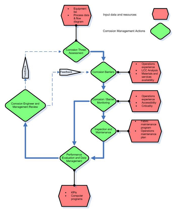
Defining an effective corrosion management strategy can be broken down into a few critical elements, as shown in the schematic10 in Figure 1.

In essence, it is a combination of clear policies and procedures, a corrosion risk assessment process, a plan for implementing inspection, maintenance, and rehabilitation strategies, and well-defined key performance indicators.

A critical component is the systematic and regular review of system performance, alongside periodic independent reviews and audits, with the overall intention being the idea of ‘getting things right’.

It is important to realise that it is the effective implementation of a corrosion management strategy – i.e. the execution of inspection, monitoring, and mitigation activities – which helps to maximise asset operation, minimise failures, and optimise costs.

Furthermore, a corrosion management strategy is more than a set of documents: it is a dynamic system that has requisite management tools to maintain asset integrity, while minimising health and environmental risks throughout an asset life cycle.

Based on our experience in auditing, developing, and implementing asset integrity management systems in the oil and gas industry, we highlight the importance of establishing and maintaining an ongoing connection between policies and the implementation of relevant activities, such as ensuring there is follow up to track down and close out recommended actions.

In addition to maintaining policies and documentation, the focus must be on practical management and identification of the resources needed to effectively implement a corrosion strategy.

We also note that challenges may arise when there is a change in asset ownership. Any implemented corrosion management strategy must be compatible with the experience and capabilities of the new owners, and may well include development of workforce competencies.

Considering the current environment, which is dominated by low oil prices, attention must be focused on existing assets, many of which are ageing.

The continuing struggle to balance cost, efficiency, and sustainability is even more difficult in the current economic climate.

In order to create a sustainable and profitable future, the industry needs to address integrity challenges in an integrated and strategic manner, always having a long-term strategy in mind.

It must learn to be proactive by preparing answers to the questions such as ‘What might go wrong?’ and ‘How can we prevent incidents?’ rather than having retrospectively to answer the questions ‘What went wrong?’ and ‘Could we have prevented this incident?’.

Although a reactive approach may provide short-term savings, it is proactive management that delivers improved operational reliability and an optimisation of the overall asset life-cycle cost.

Perhaps one way of getting answers to these questions is through learning from other industries. For example, in the aviation industry, information about any untoward incident is openly and rapidly shared across the industry.

The global pipeline industry should consider adopting a similar concept of information sharing under the banner of a common asset integrity philosophy and a unified approach to corrosion management.

This article was featured in the September edition of Pipelines International. To view the magazine on your PC, Mac, tablet, or mobile device, click here.

  1. G.Koch, N.Thompson, O.Moghissi, J.Payer, and J.Varney, 2016. Impact: international measures of prevention, application and economics of corrosion technology study. Report No. OAPUS310GKOCH, AP11272, NACE International, Houston, TX.
  2. G.Koch, M.Brongers, N.Thompson, Y.Virmani, and J.Payer, 2001. Corrosion cost and preventive strategies in the United States. FHWA-RD-01-156, McLean, VA, FHWA.
  3. City switch to Flint River water slated to happen Friday. The Flint Journal, 24 April, 2014.
  4. R. Jordan, 2016. Q&A: Stanford water expert on lessons of Flint, Michigan, crisis. Stanford News, 11 March.
  5. M.Edwards, 2015. Research update: corrosivity of Flint water to iron pipes in the city – a costly problem. Flint Water Study Updates, 29 September.
  6. S.Gosk, K.Monahan, T.Sandler, and H.Rappleye, 2016. Internal e-mail: Michigan blowing off Flint over lead in water. NBC News, 6 January.
  7. M.Gaffney, 2000. Only one survivor remains from New Mexico explosion. Lubbock Avalanche-Journal, 21 August.
  8. B.Singh, J.Britton, and D.Flannery, 2003. Offshore corrosion failure analysis – a series of case histories. Paper 03114, Corrosion 2003, NACE International, Houston, TX.
  9. B.Vielmetti, 2014. Former Shell pipeline monitor to plead guilty in airport leak. The J. Sentinel, 17 November.
  10. B.Singh, P.Jukes, B.Wittkower, and B.Poblete, 2009. Offshore integrity management 20 years on – overview of lessons learnt post-Piper Alpha. Paper OTC 20051-PP, Offshore Technology Conference, NACE International, Houston, TX.
  11. J.Soltis, M.Palmer, D.Sandana, and I.Laing, 2016. Importance of corrosion diagnosis in repeated in-line inspection-based corrosion growth assessments. Paper RISK16-8749, Corrosion Risk Management Conference 2016, NACE International, Houston, TX.

Corrosion and the Environment

The fact that corrosion does occur should not because for surprise. Almost all materials should be expected to deteriorate with time when exposed to the elements. Corrosion is a perfectly natural process, as natural as water flowing downhill. If water flowed uphill or remained stationary on a hillside, there may be cause for surprise, yet our human ingenuity can accomplish this by putting water in a closed container (pipe) and closing the bottom end, or merely freezing it. Similarly, if iron or steel were exposed to air and water, rust would be expected to develop within a matter of hours.

Full article click Corrosion and the Environment

Essential Elements of a Successful Corrosion Management Program

By Ben DuBose on 6/30/2016 3:41 PM (taken from http://www.materialsperformance.com/articles/material-selection-design/2016/07/essential-elements-of-a-successful-corrosion-management-program)

betchel

Maintaining an effective corrosion management program is essential for achieving high reliability at any oil and gas production or refining facility, according to project officials from industry contractor Bechtel.

Sameer V. Ghalsasi , a NACE International member and materials specialist at Bechtel Oil, Gas and Chemicals in Houston, Texas,  explained the most important elements of such a program in a presentation1 at the recent NACE Corrosion Risk Management Conference, held May 23-25 in Houston, Texas.

“An effective corrosion management program is necessary for successful operations,” Ghalsasi says. “This process starts as early as the conceptual design phase, and it continues throughout the design life of the facility.”

FIGURE 1: This is a sample corrosion management strategy used in a recent case at a water treatment facility. Photo courtesy of Bechtel.

FIGURE 1: This is a sample corrosion management strategy used in a recent case at a water treatment facility. Photo courtesy of Bechtel.

Identification of Corrosion Threats

In the early stages of development, a comprehensive list of all probable corrosion threats should be compiled. From there, each threat is evaluated based on process conditions, past experience, industry standards, and simulation models, if available.

For example, Ghalsasi reports that in a recent case involving a water treatment facility (Figure 1), the most probable corrosion threats to the plant were identified early in the process as carbon dioxide (CO2) corrosion, external atmospheric corrosion, and microbiologically influenced corrosion (MIC).

The determination of those threats is much simpler for brownfield projects, or expansions of existing facilities. This is because historic data are available from the operations team for that facility, and exact information about site conditions is also available.

“The operations team’s past experience plays a vital role in determining the credible threats and the mitigation measures,” Ghalsasi says. Meanwhile, identifying the threats for a greenfield project—or new facility—is more challenging. This is because only a limited amount of process data are available, and it becomes even more difficult to predict variations in the process parameters during future startup and shutdown periods, during upset conditions, and during future chemical injections.

“In those situations, the corrosion assessments are usually based upon past experience or experimental results,” Ghalsasi says.

Life-Cycle Cost Analysis

Once credible corrosion threats are identified, the next step in the process is to determine the feasibility of using low-cost construction materials—such as carbon steel (CS). This life-cycle cost analysis provides the means to assess the viability of CS.

The total cost analysis for using CS should include capital expenditures such as the costs for materials, fabrication, quality control, logistics, and procurement; operational expenditures like monitoring, inspection, maintenance, repair, materials and chemicals supply, training, and management costs; and the cost of failure. The costs of failure would include any loss of production or materials, as well as the costs of repair and punitive costs due to personnel and environmental safety incidents.

A similar analysis can also be made for considering a suitable corrosion-resistant alloy or a non-metallic material.

Looking at recent cases, Bechtel found that the most suitable construction material could vary based on the objective of the particular process unit. For large diameter pipelines that cover long distances and are designed for limited service life, CS can be economical, even with the high operating cost due to corrosion management and maintenance.

However, for pipelines that are relatively smaller and cover shorter distances, the initial savings in capital expenditures from using CS are surpassed by the operational expenditures over the service life. In that situation, using a corrosion-resistant alloy has proven to be more economical over the long run, Ghalsasi says.

Corrosion Control Strategies

Once the analysis is completed, the next step in the process of developing a corrosion management strategy is to determine the corrosion control technologies to be used. Numerous industry standards provide guidelines for the threat assessment and control selection.

One control strategy often implemented in oil and gas facilities is material selection. Depending on the predicted corrosion mechanisms, materials and/or heat treatments are chosen. Additionally, expected corrosion rates are calculated for the projected life of the unit, and a suitable corrosion allowance is selected for the service life.

Another oft-used solution can be external coatings, like paint. This is the primary defense mechanism for atmospheric corrosion. The coatings require normal maintenance, including touch-up of any damaged areas and possibly a full repainting  every 10 to 15  years to ensure that the protection is maintained.

Similarly, linings are effective barriers for internal corrosion due to process fluid. These internal linings often require special application processes and equipment, and they are normally suitable for large tanks and vessels. Meanwhile, cladding with a corrosion-resistant alloy can be a solution when maintenance of other internal linings is not practical.

Coating is often selected in conjunction with cathodic protection (CP), which can be used on buried or immersed metallic components and structures.  Sacrificial anode (passive) and impressed current (active) are two popular techniques of CP, Ghalsasi says.

Other solutions include corrosion inhibitors and chemical injection. Within the inhibitors, neutralizing inhibitors and filming corrosion inhibitors comprise the most popular categories. Neutralizing inhibitors control the pH of the process fluid, while filming corrosion inhibitors form a protective barrier on metal surfaces.

“Inhibitor selection is perhaps the most critical step in the development of a successful corrosion inhibition program,” Ghalsasi says.

Some factors considered in inhibitor selection are the uninhibited corrosion rate, wall shear stress, temperature, the total dissolved solids, the solubility of the inhibitor in water, the inhibitor’s compatibility with other production chemicals and with handling and storage materials, and environmental regulations.

The final inhibitor selection then typically involves laboratory or field testing.

“Focusing solely on the efficiency of a corrosion inhibitor is not sufficient,” Ghalsasi says. “The availability of the inhibitor plays an equally important role in corrosion management. The inhibitor availability also takes into account any practical limitations in the deployment of a corrosion inhibitor into the system.”

Meanwhile, various types of chemicals can also be injected to reduce the corrosion rate, including biocides and oxygen scavengers. However, some chemicals may promote undesired corrosion effects if used improperly.

“In order to avoid undesirable effects, a chemical injection program is almost always coupled with a monitoring and inspection program,” Ghalsasi says. “For petroleum refineries, NACE SP01142 provides guidelines for the location, design, performance verification, and the monitoring of the injection and process mix points.”

Corrosion Monitoring and Inspection

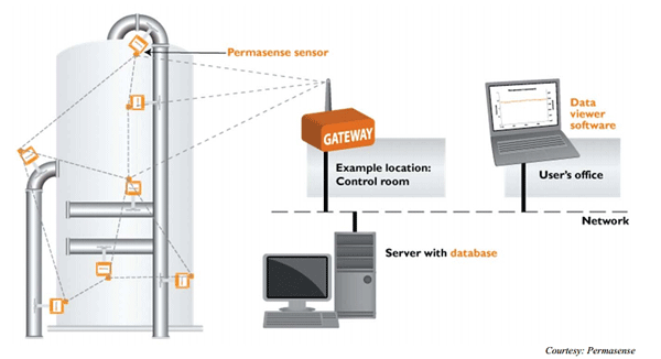
FIGURE 2: A corrosion monitoring system is one of many online methods now being used to combat corrosion. Photo courtesy of Permasense.

FIGURE 2: A corrosion monitoring system is one of many online methods now being used to combat corrosion. Photo courtesy of Permasense.

Once corrosion threats and the respective controls are identified, the next step in management is to select proper monitoring and inspection techniques to determine the effectiveness of the deployed barriers. Some barriers are active and require constant surveillance or monitoring, while routine inspection may be adequate for other barriers.

Depending on the technique used, corrosion monitoring can detect corrosion while it is happening, whereas inspection reveals the end effects of corrosion that have already taken place.

“Both techniques are essential for a successful corrosion management program, and they allow corrosion engineers to take the necessary actions to prevent future corrosion losses,” Ghalsasi says.

Some of the most common monitoring techniques include online methods such as mass loss coupons, electrical resistance (ER) probes, linear polarization resistance (LPR) probes, and hydrogen probes. A new technology involving the use of online UT measurements and data transfer through a wireless router can provide high precision rate measurements, allowing trouble to be addressed before too much material has been lost (Figure 2).

Additionally, sampling stations are sometimes provided at key locations in the process facility. With sampling stations, the extracted process fluid can then be further analyzed for electrochemical properties—which, in turn, can give a greater understanding of the corrosion characteristics of the process fluid.

“This type of monitoring is offline monitoring,” Ghalsasi says of the sampling stations. “While it allows greater flexibility and reliability, it does require more time.”

Meanwhile, some of the commonly used inspection techniques are visual inspection, radiographic testing (RT), ultrasound testing (UT), eddy current testing (ECT), magnetic particle testing (MT), and liquid penetrant testing (PT).

Program Performance Review and Management

The final step in Bechtel’s suggested process is the program performance review, which involves receiving feedback on the reporting and analysis of measurements obtained from chemical injection, corrosion monitoring, and inspection. This step also acts as the interface between the corrosion engineering team, operations team, and facility management.

“Hence, the information reported should be meaningful to all interested parties,” Ghalsasi says.

“Apart from communicating the technical details such as inhibitor qualities, corrosion rates, and wall thickness measurements, it is equally essential to talk in terms of cost, man-hours, and schedule,” he adds.

Ghalsasi also noted that several key performance indicators (KPIs), such as the availability of corrosion inhibitors, could assist in the effective reporting of information obtained in the corrosion management program. One example is a cost of corrosion KPI, where the corrosion damage sustained during a monitoring cycle is converted into an equivalent dollar value. Another is an equipment maintenance completed KPI, which measures the percentage of maintenance activities completed in a given cycle.

“Communication with facility operations staff plays a vital role in the development of this strategy,” Ghalsasi says. “Historic data and past experience obtained from the facility are of paramount importance in this process.”

The information reported in terms of KPIs is then reviewed and analyzed in order to take any necessary corrective actions.

“The types of corrosion threats and their controlling techniques can vary largely depending on the nature of the facility, its location, and the degree of criticality of a system, piece of equipment, and/or associated piping,” Ghalsasi says.

“There is no single flowchart or one procedure that can cover all the requirements,” he adds. “However, these components can form a central theme for a successful corrosion management program.”

Contact Sameer V. Ghalsasi, Bechtel—e-mail: svghalsa@bechtel.com.

References

1 S. Ghalsasi, B. Fultz, R. Colwell, “Primary Constituents of a Successful Corrosion Management Program,” NACE Corrosion Risk Management Conference, paper no. RISK16-8734 (Houston, TX: NACE International, 2016).

2 NACE SP0114-2014, “Refinery Injection and Process Mix Points” (Houston, TX: NACE, 2014).

Novel Technique Studies Water Pipe Corrosion Caused By Microbes

Principles of Electrochemistry Applied to Corrosion

Although corrosion can take several forms, the mechanism of attack in aqueous environments involves some aspect of electrochemistry. There is a flow of electricity from certain areas of a metal surface to other areas through a solution capable of conducting electricity, such as seawater or fresh water. The term anode is used to describe that portion of the metal surface that is corroded and the term cathode is used to describe the metal surface from which current leaves the solution and returns to the metal.

Full article click Principles of Electrochemistry Applied to Corrosion

Polarization

As is the case with other chemical reactions, the driving force of a corrosion reaction is related to the difference in energy between an initial equilibrium that is higher in energy than the final equilibrium. As corrosion action proceeds, this difference in energy tends to decrease as a result of the effects of the products of anodic and cathodic reactions in the vicinity of the corrosion sites. The cathodic reaction, and with it the overall corrosion reaction, would slow down if, for example, the hydrogen product of the cathodic reaction were not removed by evolution as gas or some reaction involving oxygen. This slowing down is said to be the result of cathodic polarization.

Full article click Polarization